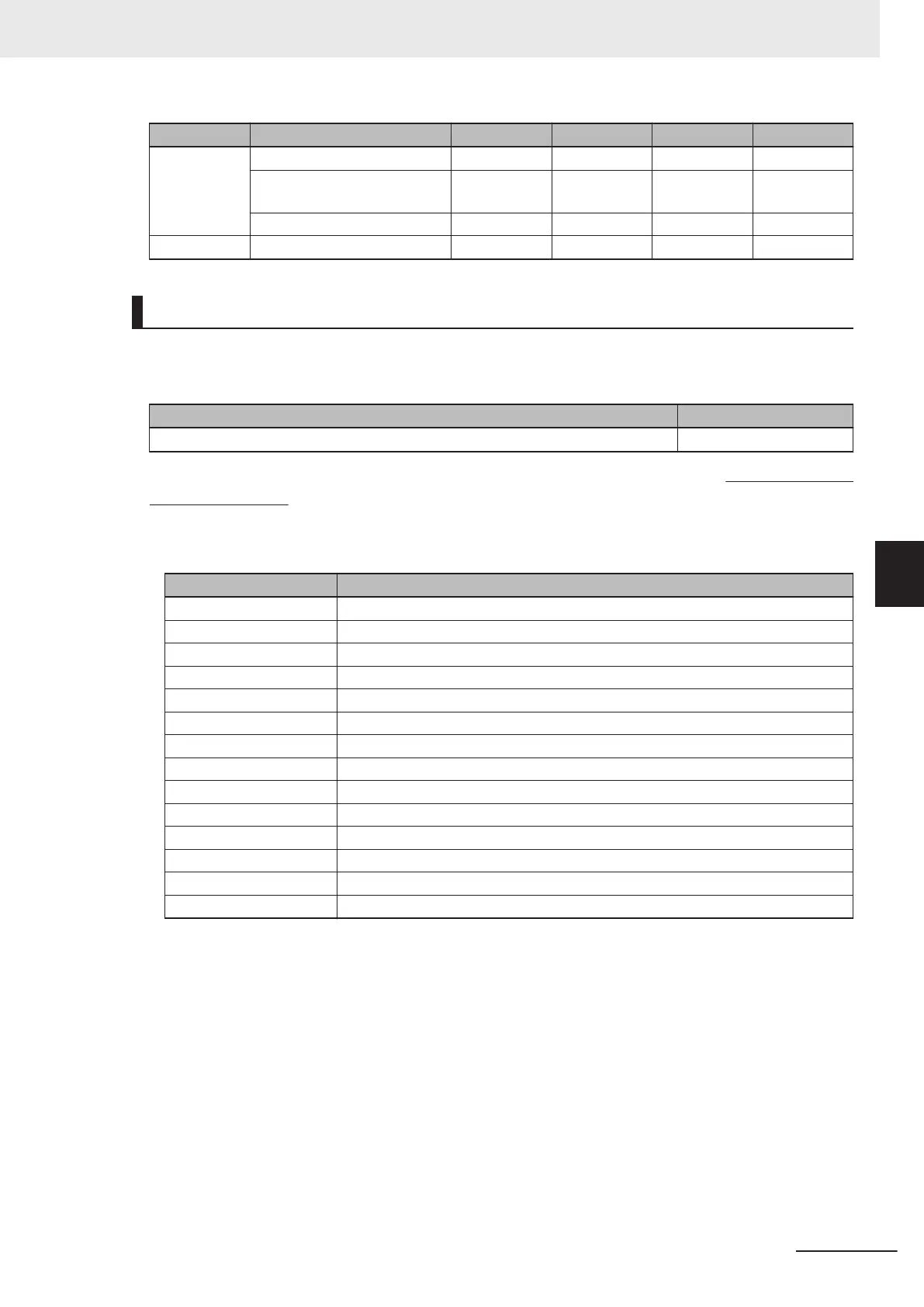
Member Name Data Type Bit Number Data Length Byte Offset
32 bit Total Read Cycle Time 0 - 15 2 byte
Number of Decodes in Read
Cycle
0 - 7 1 byte
Number of Decode Reports 0 - 7 1 byte
RAW Input Data 16 byte 44 byte
Output Assembly (Instance ID: 197)
The Output Assembly can send several commands to the code reader.
Output Assembly Member Structure
Member Name Size (Bytes)
COMMANDS 4
Total Size: 4 Bytes
Member Description
• Commands
An explanation of commands that can be sent to the code reader.
Bit Command
0 Run Mode
1 Trigger
2 Enable Matchcode
3 Reset General Fault
4 Clear No Read Read Cycle Counter
5 Clear Mismatch Read Cycle Counter
6 Clear No Read Counter
7 Clear Trigger Counter
8 Clear Matchcode Counter
9 Clear Mismatch Counter
10 Output 1
11 Output 2
12 Output 3
13 - 31 Reserved
・Run Mode
Enables / Disables Read Cycle. Immediately after the code reader is started, Read Cycle will be en-
abled regardless of this command.
0 = Read Cycle Disabled. No trigger can be accepted. However, other commands can be executed. 1
= Enables Read Cycle.
・Trigger
Executes Read. The code reader recognizes this bit changing from 0 to 1 as the rising edge of the
trigger and its change from 1 to 0 as the falling edge of the trigger.
・Enable Matchcode
Enable / Disable the Matchcode function. Immediately after the code reader is started, the previously
saved setting is in effect regardless of this command.
0 = Disable Matchcode function.
1= Enable Matchcode function.
Appendices
A - 29
V430-F Series Autofocus Multicode Reader User Manual for Communication Settings
A-2 EtherNet/IP Detailed Specifications
A
A-2-1 Assembly Memory Allocation

 Loading...

