・Reset General Fault
If an error occurs on the code reader, after resolving the error, this bit is used to reset the Fault Code
Area of the Input Assembly.
・Clear No Read Read Cycle Counter
Resets the No Reads per Read Cycle counter to 0.
・Clear Mismatch Read Cycle Counter
Resets the Mismatch per Read Cycle counter to 0.
・Clear No Read Counter
Resets the No Reads counter to 0.
・Clear Trigger Counter
Resets the Trigger counter to 0.
・Clear Matchcode Counter
Resets the Matchcode counter to 0.
・Clear Mismatch Counter
Resets the Mismatch counter to 0.
・Output 1
Turns Parallel OUTPUT 1 Signal ON.
・Output 2
Turns Parallel OUTPUT 2 Signal ON.
・Output 3
Turns Parallel OUTPUT 3 Signal ON.
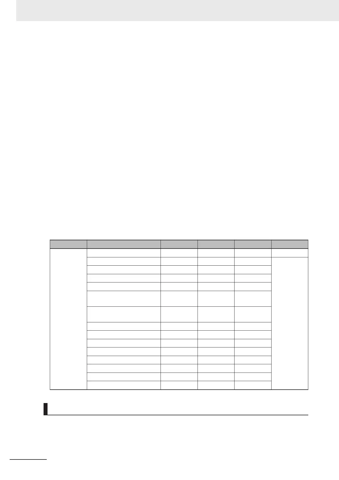
Assembly Memory Allocation
Member Name Data Type Bit Number Data Length Byte Offset
32 bit Commands DINT 4 Byte 0
Run Mode 0 1 bit
Trigger 1 1 bit
Enable Matchcode 2 1 bit
Reset General Fault 3 1 bit
Clear No Read Read
Cycle Count
4 1 bit
Clear Mismatch Read
Cycle Count
5 1 bit
Clear No Read Count 6 1 bit
Clear Trigger Count 7 1 bit
Clear Matchcode Count 8 1 bit
Clear Mismatch Count 9 1 bit
Output 1 10 1 bit
Output 2 11 1 bit
Output 3 12 1 bit
Reserved 12 - 31 19 bit
Output Assembly (Legacy) (Instance ID: 198)
The Output Assembly (Legacy) can be used to send multiple commands and Command Echo for fixed
data to the code reader.
Appendices
A - 30
V430-F Series Autofocus Multicode Reader User Manual for Communication Settings

 Loading...

