Mismatch or No Read
The assigned output signal turns ON when one of the following conditions is met.
• On No Read (NOREAD)
• If using the Matchcode function, when it does not match with the master symbol.
• Triggered Mode must be External or Serial
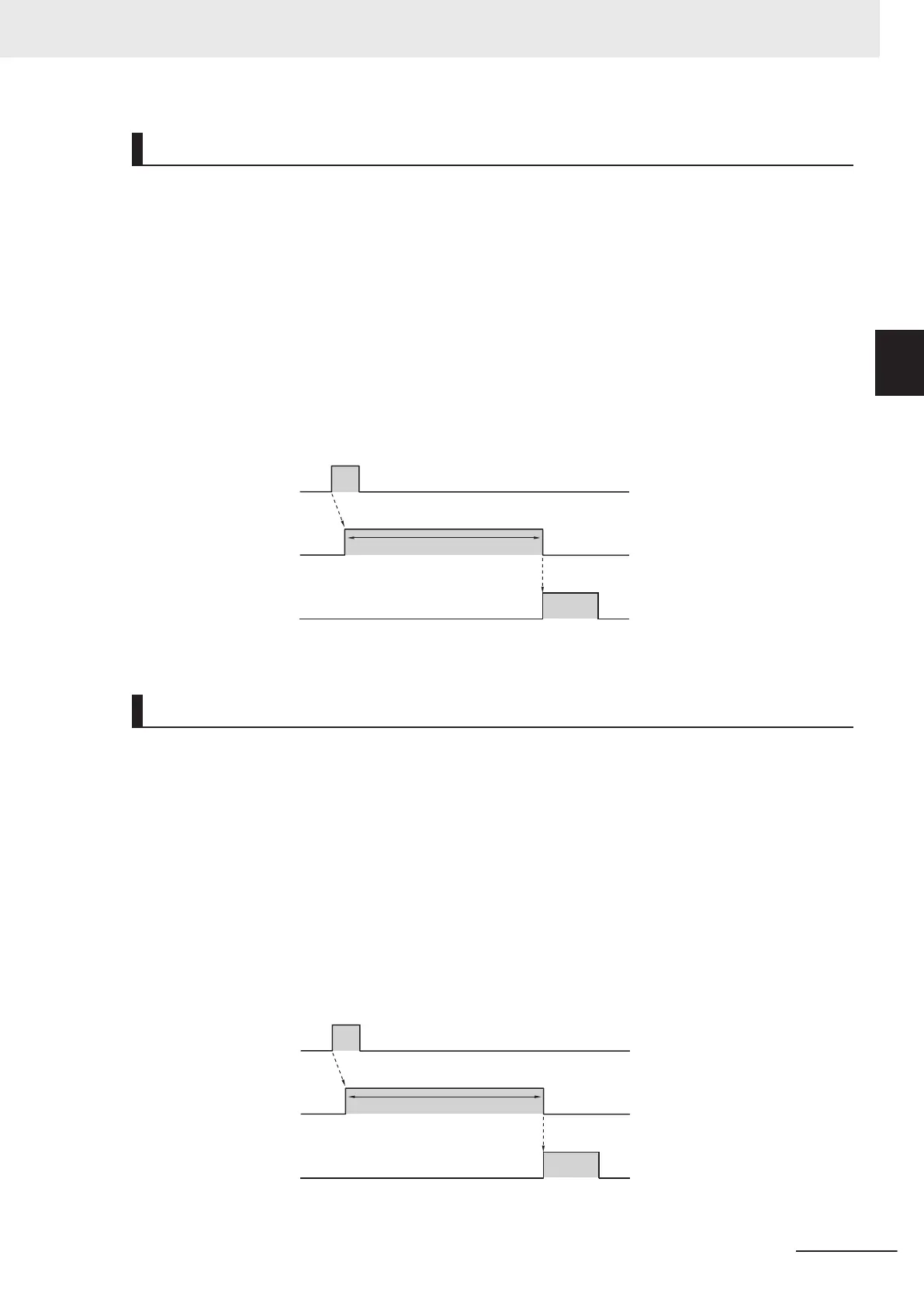
Below is an Output assignment example and Timing chart.
[Example assignment of OUTPUT signals]
• Output 1: In Read Cycle
• Output 2: Mismatch (or No Read) Output Mode: Pulse
For how to set up the Output signal assignments, please refer to How to Assign the Output Signals on
page 2 - 10
<Timing Chart>
1. Trigger input
(TRIG signal)
2.
Output1
In Read Cycle
3.
Output2
Mismatch
(or
No Read)
OFF
ON
OFF
ON
OFF
ON
In Read Cycle
Turns ON if No Read. *1
Read executed by Trigger Input.
*1 You can change the length of time the signal is ON. For further information, please refer to
2-1-8 Change the ON/OFF timing of the Output Signal (Output 1 to 3) on page 2 - 17.
Match (or On Good Read)
The assigned output signal turns ON when one of the following conditions is met.
• On Good Read
• If using the Matchcode function, when it matches with the master symbol.
Below is an Output assignment example and Timing chart.
[Example assignment of OUTPUT signals]
• Output 1: In Read Cycle
• Output 2: On Match (or On Good Read) Output Mode: Pulse
For how to set up the Output signal assignments, please refer to How to Assign the Output Signals on
page 2 - 10
<Timing Chart>
• Trigger Input → On Good Read
1. Trigger input
(TRIG signal)
2. Output1
In Read Cycle
3. Output2
Match
(or Good Read)
OFF
ON
OFF
ON
OFF
ON
In Read Cycle
Turns ON on Good Read *1
Read executed by Trigger Input.
2 Controlling Operation and Data Output with Parallel
2 - 11
V430-F Series Autofocus Multicode Reader User Manual for Communication Settings
2-1 Controlling Operation and Data Output
with Parallel
2
2-1-7 Change the Assignments for the Output Signal (Output 1 to 3) ON Condition

 Loading...

