F
-
4300 CLAMP
-
ON ULTRASONIC FLOW METER
ONICON Incorporated 727.447.6140 Page 19 onicon.com
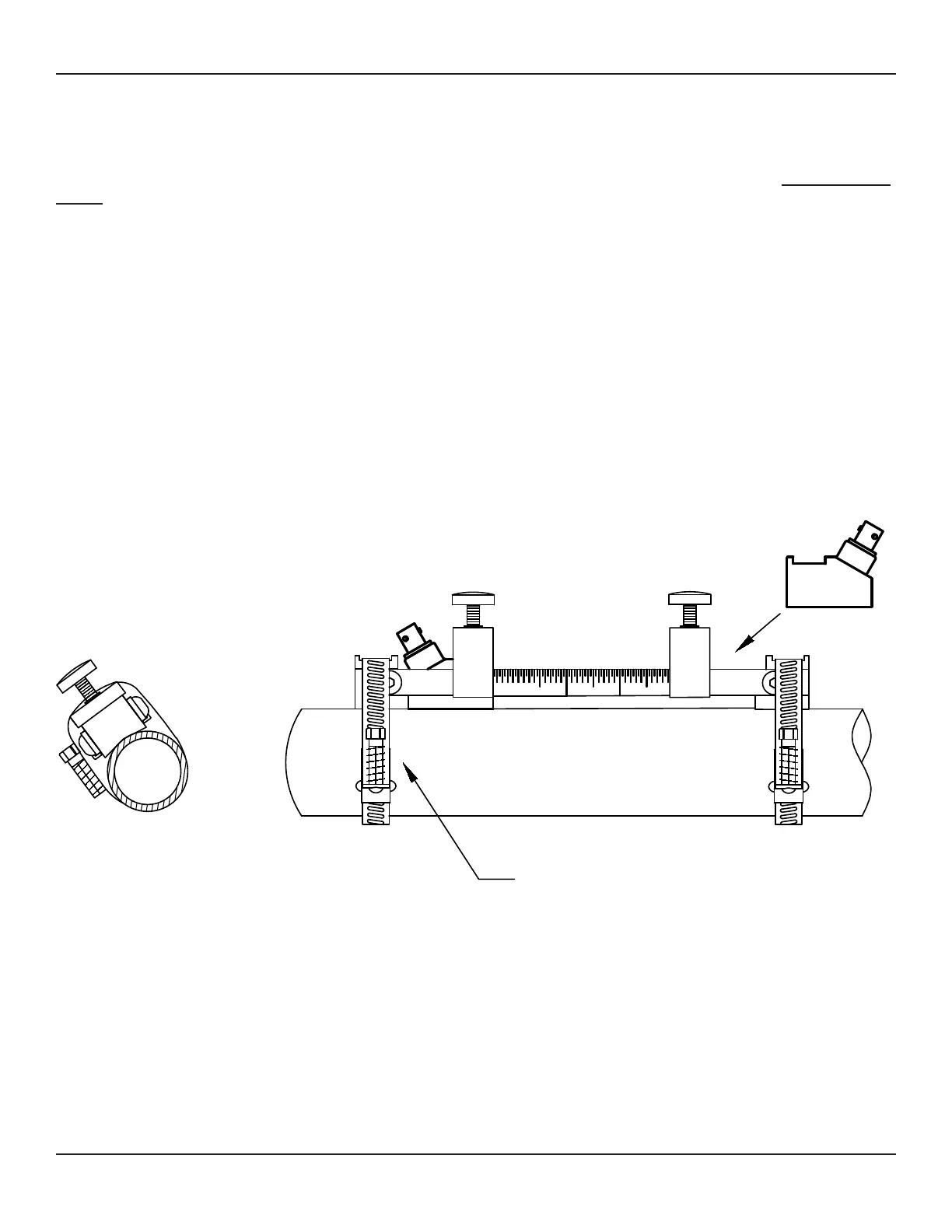
3.3.2 10 Series Mechanical Installation
3.3.2.1 Preparing the Pipe for 10 Series Transducers
Pipe
Pipe
Transducer
END VIEW
Adjustable Stainless
Steel Strap
Once a suitable section of straight pipe has been located, the pipe surface must be prepared. Refer to the
document provided with the installation hardware to determine the transducer spacing dimensions.
of site preparation is to eliminate any discontinuity between the sensor and the pipe wall, which would prevent acoustical
coupling. A sanding block is included with every meter to facilitate proper pipe preparation.
between transducer faces.
IMPORTANT NOTE
Always install hardware at the 2:00 to 4:00 or 8:00 to 10:00 position on horizontal pipes. This prevents the ow
meter from being aect by air trapped at the top of the pipe.
IMPORTANT NOTE
The 10 Series transit-time transducers should be installed with the cable connections pointed away from each other,
as shown in the drawing below.