PUMA T2
Technical Handbook
NiCd, NiMH and Li-ion batteries
Page 122 OTE Proprietary information
P/N: 779-0306/01
Revision 03
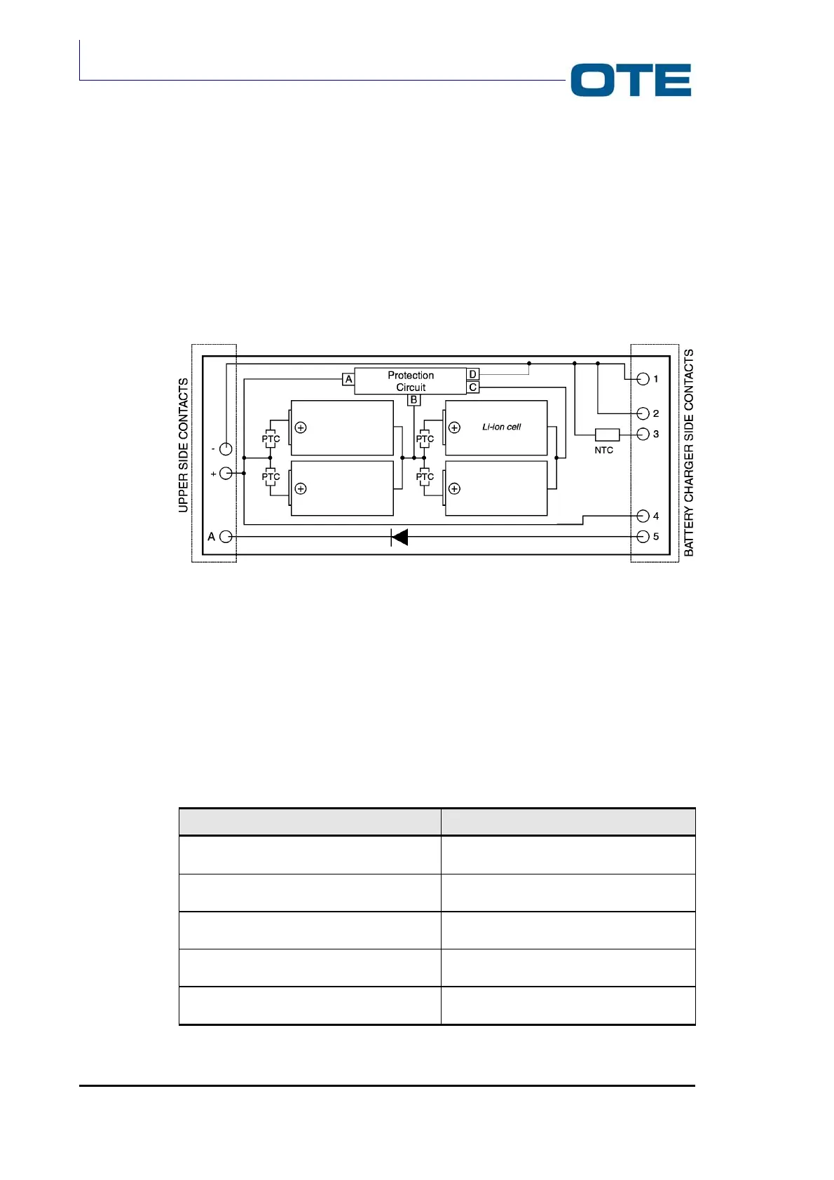
D.3 BATTERY PACK LAYOUT AND PROTECTION CIRCUIT
The battery pack circuitry is based on two couples of parallel cells of Li-ion
connected in series.
This architecture permits to reach a DC voltage of 7.4 V and a nominal capacity of
2700 mAh.
A detail of the structure is given below.
Fig. D.6: Block diagram of the protection circuit
The electronic protection circuit prevent the cells from dangerous discharging or
charging cells, short circuits or current overloads. The electronic circuit is equipped
with NTC and PTC (Negative Temperature Coefficient resistance and Positive
Temperature Coefficient resistance).
The electrical characteristics of the protection circuit are given in Tab. D.3; the
values refer to a single Li-ion cell.
Tab. D.3: Electrical characteristics
Description Value
Over-voltage detection 4,35 ± 25 mV
5 mV
Over-voltage cut-off 4,15 V ± 50 mV
5 mV
Nominal discharging voltage 2,30 ± 80 mV
5 mV
Nominal cut-off voltage 3,00 V ± 100 mV
5 mV
Over-current detection 0,300 V ± 20 mV
5 mV