PUMA T2
Technical Handbook
Technical description
P/N: 779-0306/01
Revision 03
OTE Proprietary information
Page 45
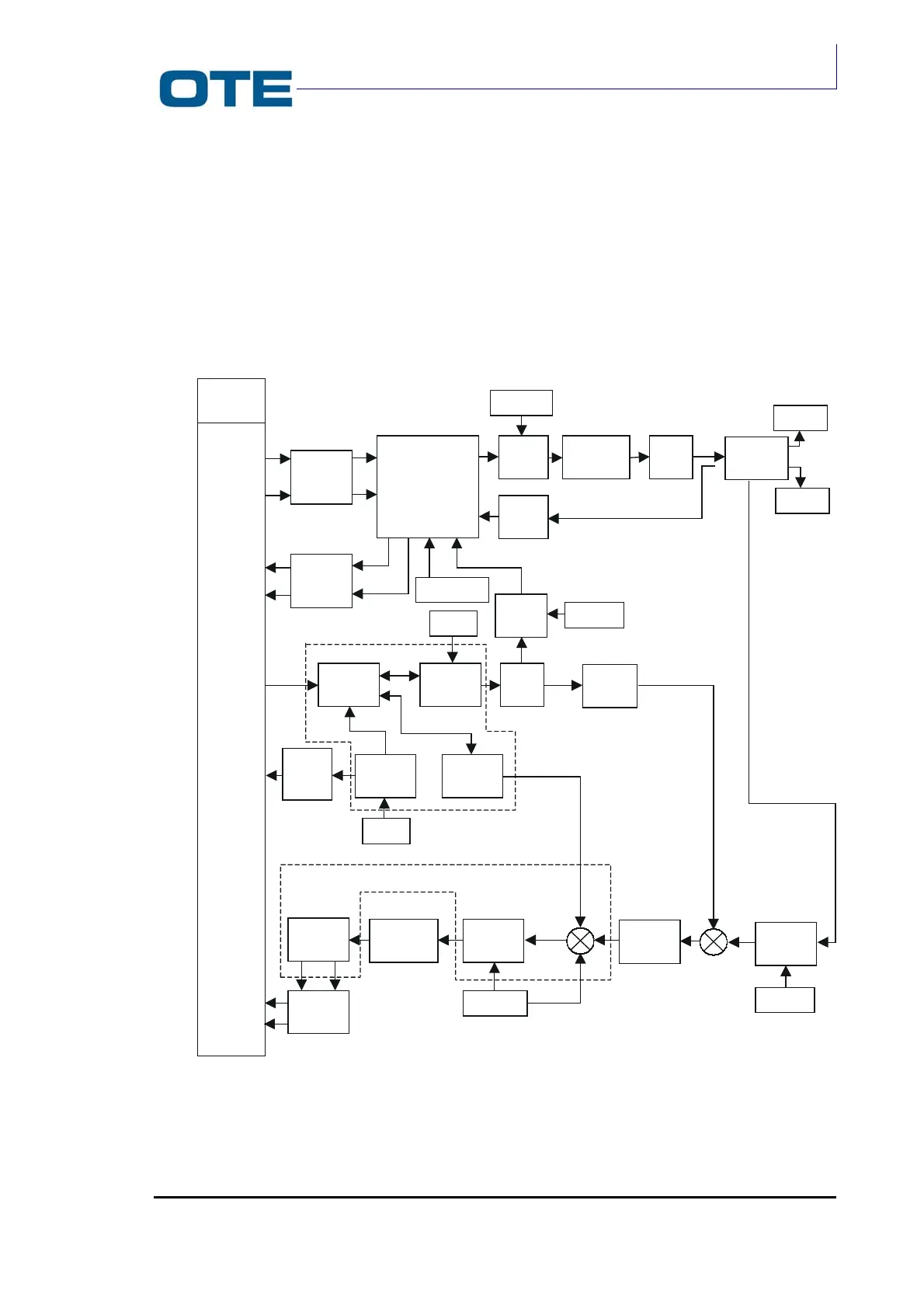
2.6 RADIOFREQUENCY SECTION
The RT board contains the circuitry for signal reception and transmission. The RT
board is made up of two sections: one contains the circuitry for transmission and
the other for reception. The RT board contains a switch block that allows frequency
changes from the receiving to the transmitting mode (see Fig. 2.3).
Fig. 2.3: RT board functional block diagram
IQ AMP
LINEARIZER
I
TX
Q
TX
I
F
Q
F
I
o,
Q
o
,V
I
,V
q
DRIVER PAATT 1
FILTER
+SW
ATT 2
VCOH
Foh
LO
SW
AMP
LOTX
PLL
VCOL
Fol
V
T1,
V
T2
IQ DEM
I
F
Q
F
AMP
VTCXO
Fref
TXGain
Fcnt
I
RX
Q
RX
Fref
FILTER
AMP FI
Fifh
FILTER
LNA
AMP
LORX
V
R1,
V
R2
RXGain
Fref
AMP
Fref
AD607
SINT
ANT1
ANT2
IQ
FILTER
CONN.
RT-BB
BSW