PUMA T2
Technical Handbook
Technical description
P/N: 779-0306/01
Revision 03
OTE Proprietary information
Page 37
The base band logic circuits communicate with the external accessory devices by
means of the flex connector. Physically, this is made up of a 30-pin in-line female
connector, with associated protection diodes and end resistors.
Tab. 2.1 shows the allocations of the interface signals on the flex connector and
their meaning.
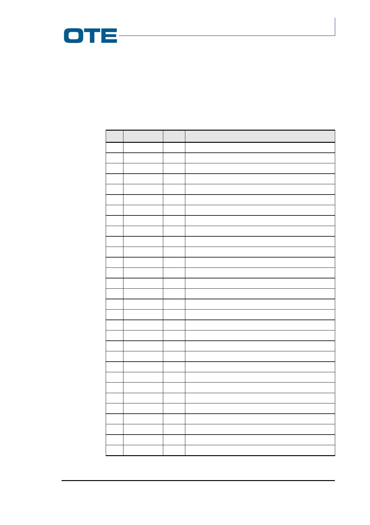
Tab. 2.1: Flex connector interface signals.
Pin Name Type Description
1 SERVICE OUT Service line (open mP collector output)
2 AP-EXT OUT External loudspeaker
3
PTT-EXT
IN
External PTT
4 ANT-EST IN External antenna presence
5 TXD OUT TX external asynchronous serial port
6 RXDD IN RX external asynchronous serial port
7 GND
8 AVVISO OUT Call inform
9 ENBFOUT OUT Enabling low frequency out the vehicular set
10 P-AUX IN Analogical signal for signallings toward mC
11 VBI-EXT OUT External devices battery power
12 PRES-AL IN External power supply presence
13 ON/OFF OUT Switch command on/off (from the on switch)
14 MIC-EN IN Differential external microphone
15 MIC-EP IN Differential external microphone
16 VCC OUT VCC towards potentiometers
17 VOL IN Command volume control
18 CAN1 IN Command channel switch
19 CAN2 IN Command channel switch
20 CAN3 IN Command channel switch
21 CAN4 IN Command channel switch
22 AP-IN1 OUT Internal loudspeaker of the differential signal 1
23 AP-IN2 OUT Internal loudspeaker of the differential signal 2
24 P-AUX2 IN Analogical signal for signalling external audio accessory
25 PTT IN Internal command PTT
26 PUSH IN Internal command Push
27 ALARM IN Internal command Alarm
28 RED LED OUT Internal red led activation
29 GREEN LED OUT Internal green led activation
30 GND OUT