PUMA T2
Technical Handbook
Technical description
P/N: 779-0306/01
Revision 03
OTE Proprietary information
Page 47
ATT1
This attenuator allows regulating the TX gain by controlling the TX gain value. TX
gain controls the current in the Pin diodes used in that stage. ATT1 acts on the
level of the transmitter noise.
DRIVER, PA
Amplification of the signal; with RF2105L and the mosfet 25K2974.
SW + FILTER
This block includes the RX/TX switch, harmonic suppressor filter, the antenna
switch. The overall loss is about 1dB.
ATT2
This attenuator regulates the signal level towards the linearizer.
IFQF AMP
This block amplifies the IF and QF signals coming from the reaction chain of the
linearizer.
LNA
This amplifier is the first stage of the amplifier, with a 13 dB gain in the band of the
received signal. It is made up of one active stage and end electronic tuning three
cells filter. VR1, VR2, allows the tuning.
FILTER AT Fifh
This is a quartz filter between two active stages with a 15 kHz, –3dB band.
Therefore, it is necessary to cover the signal distortion with a static equalizer in
base band.
FILTER AT Fref
LC low-pass filter.
IQ FILTER
Filter band 12 kHz.
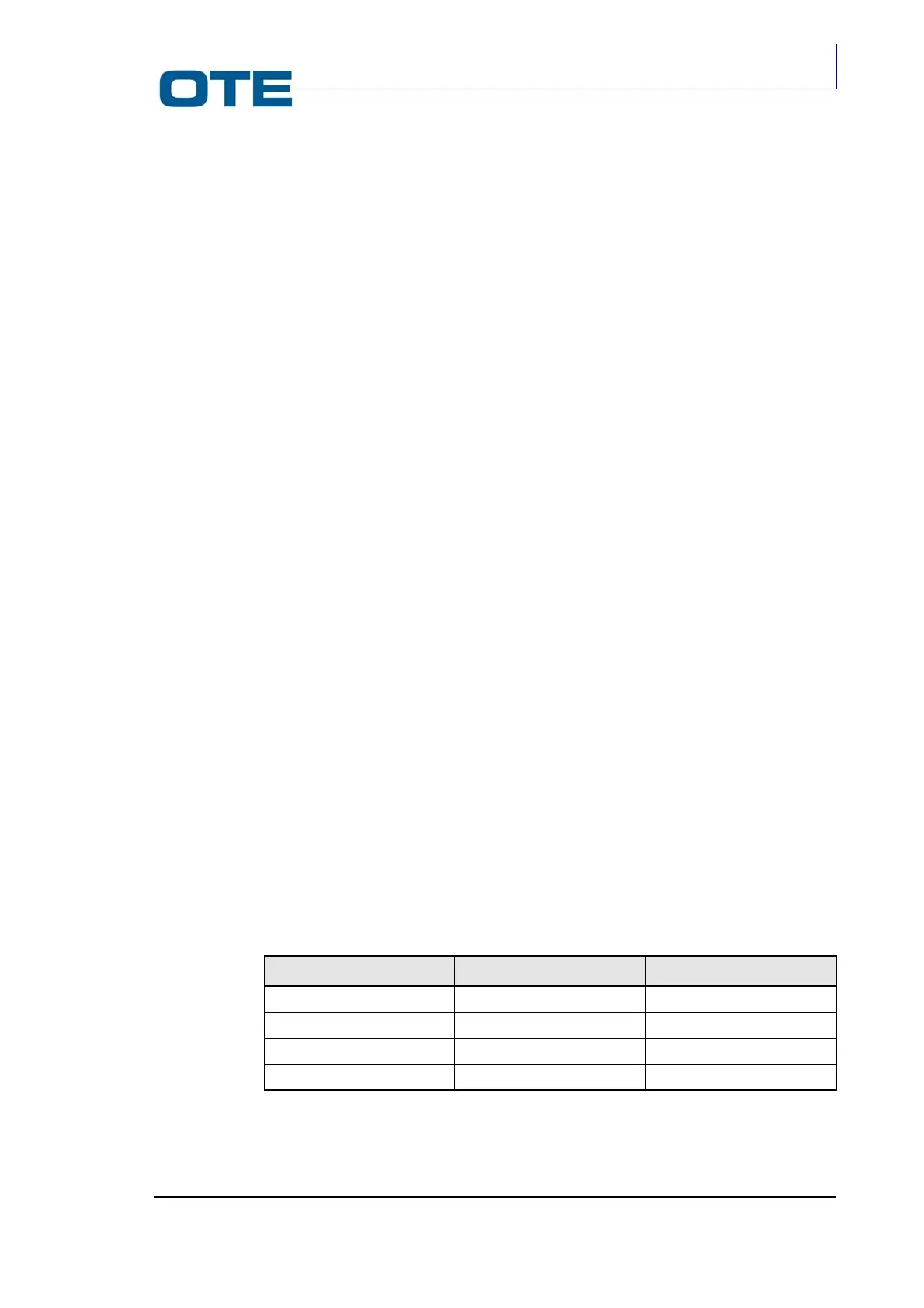
Tab. 2.3: Signal frequnces
Version Fifh Fref
PUMA T2-400 90 MHz 14.4 MHz
PUMA T2-430 90 MHz 14.4 MHz
PUMA T2-470 90 MHz 19.8 MHz
PUMA T2-870 45 MHz 14.4 MHz