PUMA T2
Technical Handbook
NiCd, NiMH and Li-ion batteries
P/N: 779-0306/01
Revision 03
OTE Proprietary information
Page 127
Three contacts are present on the lower side:
1. Negative
2. Positive
3. Auxiliary
Fig. D.12: Lower Side Battery Contacts
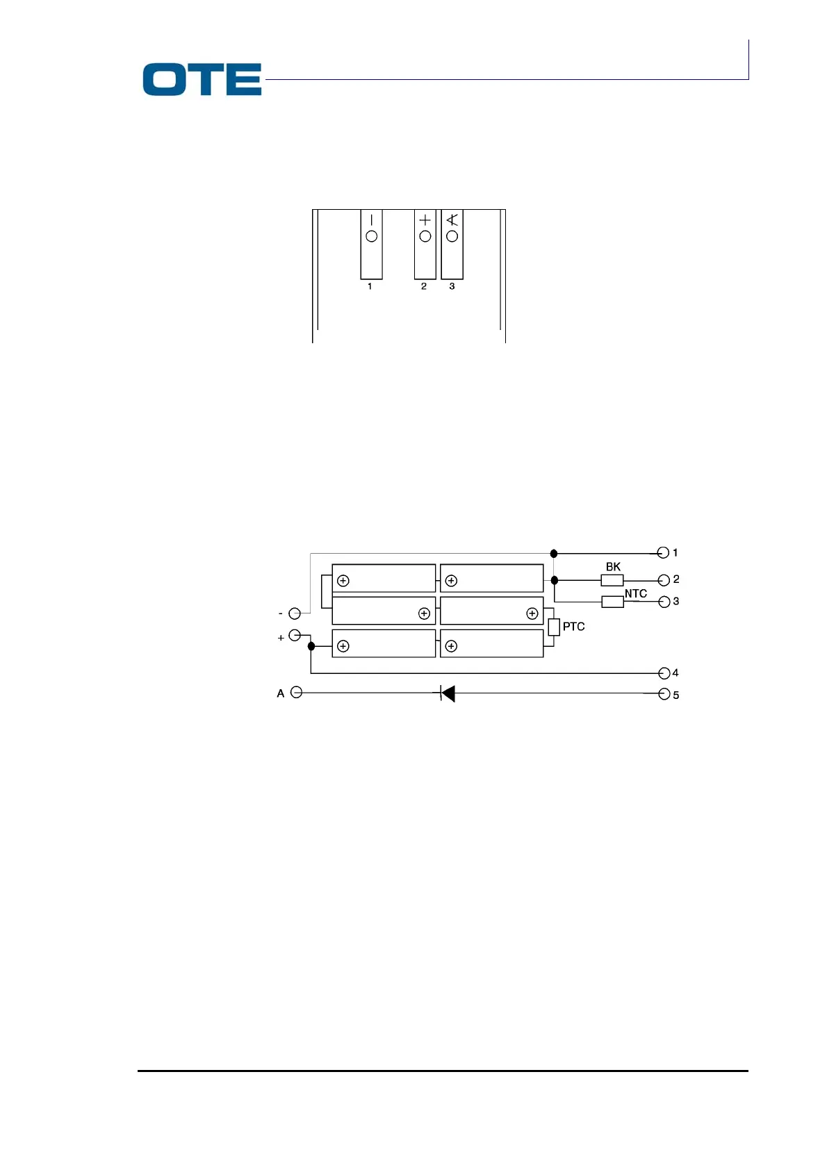
D.4.4 Internal scheme
Inside the pack six battery cells are placed as in the following scheme in Fig. D.13.
Fig. D.13: Internal circuitry of the pack
The thermal protection (PTC) placed in series with the cells prevents a high current
from flowing in the cells. The impedence of the component must start to rise when
a current of 5 Ampère is flowing in the battery pack.
An NTC must be placed directly over the cells to be able measure its temperature
during the charging phase. Its impedence must be 4.7 KΩ at 25 °C.
A resistor must be placed between contacts 1 and 2 in order to allow battery kind
identification.
A diode (3 Ampere) must be present between contact 5 and A, as indicated.