108
Oxford Technical Solutions
Operating principles
This short section gives some background information on the components in the RT and
how they work together to give the outputs. A short overview of the algorithm is given
and some explanation of how the software works. The section is provided as ‘interesting
information’ and is not required for normal operation.
Internal components
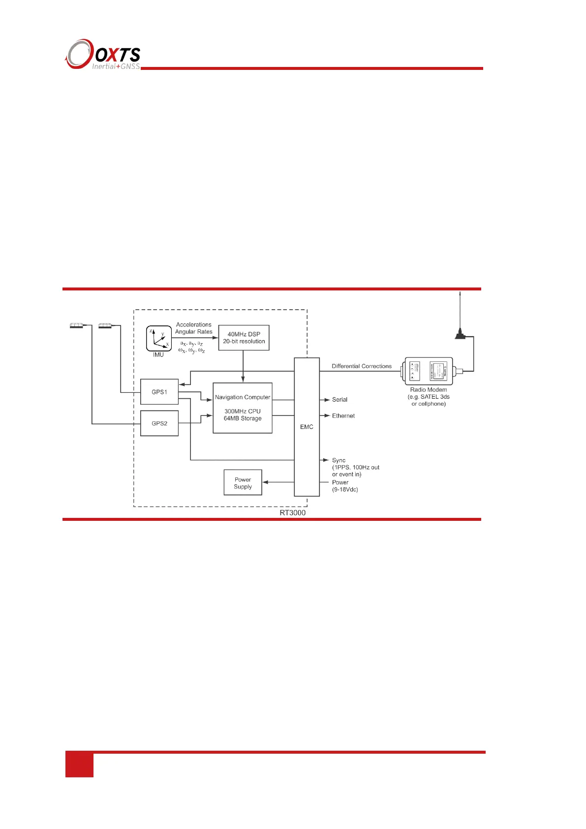
Figure 49 gives a schematic view of the components in the RT system.
Figure 49. Schematic showing the internal components of the RT
The schematic shows the layout for a dual antenna system, the second GNSS (GNSS2)
and the second antenna are not fitted on single antenna systems.
The accelerations and angular rates are measured in the inertial measurement unit. The
accelerometers are all mounted at 90° to each other so they can measure each direction
independently. The three angular rate sensors are mounted in the same three directions
as the accelerometers. A powerful, 40 MHz floating point DSP controls the ADC and,
through advanced signal processing, gives a resolution of 20-bits. Digital anti-aliasing
filters and coning/sculling motion compensation algorithms are run on the DSP.
Calibration of the accelerometers and angular rate sensors also takes place in the DSP;
this includes very high-precision alignment matrices that ensure that the direction of the
acceleration and angular rate measurements is accurate to better than 0.01°.