50
Oxford Technical Solutions
9 Digital ground Reserved
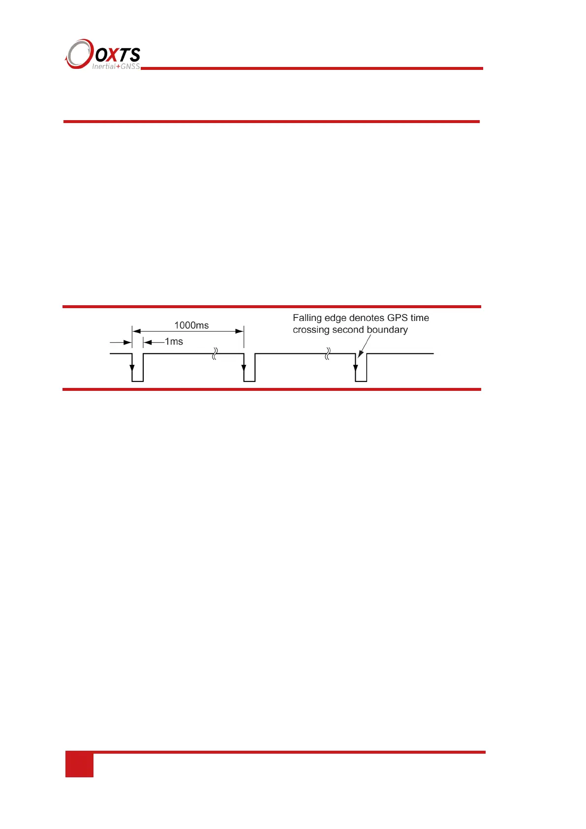
1PPS output
The 1PPS output is a pulse from the GNSS receiver. The falling edge of the pulse is the
exact transition from one second to the next in GPS time. The pulse is low for 1 ms, then
high for 999 ms and repeats every second.
On RT2500 and RT2502 products the 1PPS is only output when the GNSS has a valid
position measurement. With RT2002, RT3000 and RT4000 products the 1PPS will
always be output.
Figure 15. 1PPS waveform
The output is a low-voltage CMOS output, with 0.8 V or less representing a low and
2.4 V or more representing a high. No more than 10 mA should be drawn from this
output. Older models have no protection on this output (protection circuitry would
disturb the accuracy of the timing). New models (post-September 2013) have limited
protection.
Event input
The event input can be used to time events, like the shutter of a camera or a brake switch.
The event input has a pull-up resistor so it can be used with a switch or as a CMOS input.
The input sees less than 0.8 V as low and more than 2.4 V as high. There is no protection
on this input (protection circuitry would disturb the accuracy of the timing). Keep the
input in the range of 0 V to 5 V.
By default the maximum event rate is 1 Hz for 100 Hz products and 4 Hz for 250 Hz
products. This can be increased to 50 Hz by selecting one or both the Output on falling
edge of trigger and Output on rising edge of trigger check boxes on the Ethernet
Output window. This is accessed from the Options page in NAVconfig (see “Ethernet
output” on page 86 of this manual).
Trigger information can be found in status message 24 and 43 (output over NCOM and
CAN) for the low-rate triggers. The fast trigger information can only be output over
NCOM.