33
Operation
The front panel label and LEDs convey some basic information that aid configuration
and troubleshooting. Once power is applied, the RT requires no further input from the
user to start logging and outputting data.
This section covers some basic information required for operation of the RT.
Front panel layout
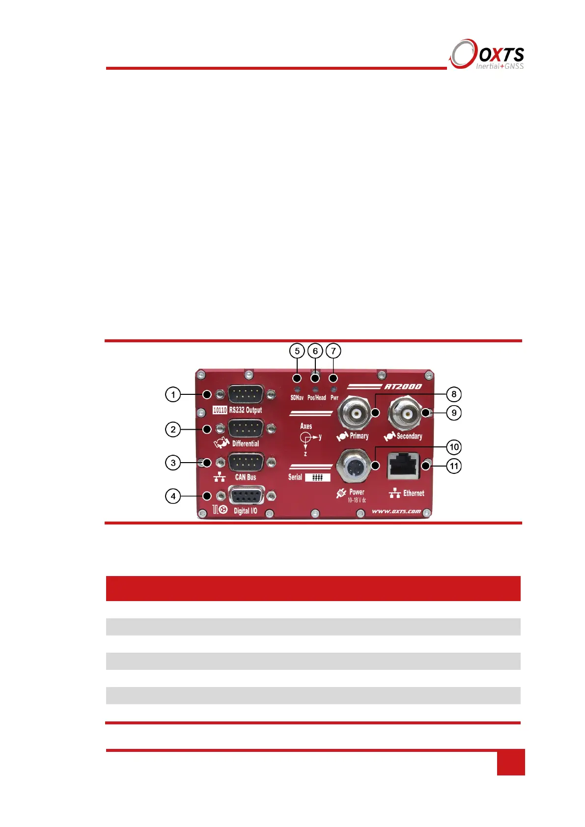
Figure 4 and Figure 5 show the layouts of the RT front panels. Table 11 lists the parts of
the RT2000 front panel labelled in Figure 4 and Table 12 lists the parts of the
RT3000/RT4000 labelled in Figure 5. For single antenna models, the secondary antenna
connector is not connected internally.
Figure 4. RT2000 front panel layout
Table 11. RT2000 front panel descriptions
Label no. Description
1 RS232 serial port
2 Radio port
3 CAN port
4 Digital I/O port
5 SDNav LED
6 Pos/Head LED
7 Pwr LED