46
Oxford Technical Solutions
Table 27. In-line coupler connections
Socket 1 Straight socket 2 Crossed socket 2
Pin 1 Pin 1 Pin 6
Pin 2 Pin 2 Pin 3
Pin 3 Pin 3 Pin 2
Pin 4 Pin 4 –
Pin 5 Pin 5 –
Pin 6 Pin 6 Pin 1
Pin 7 Pin 7 –
Pin 8 Pin 8 –
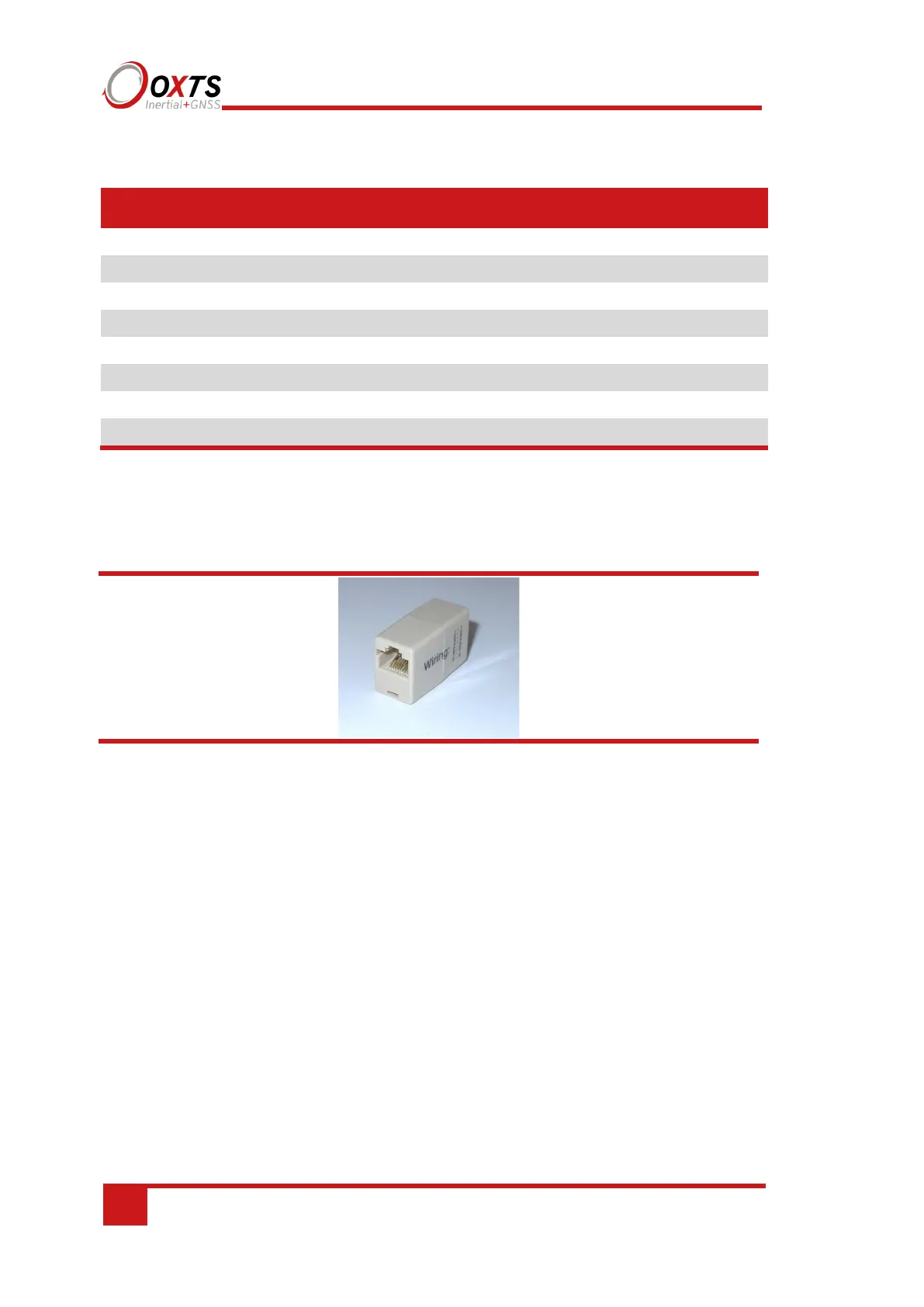
A typical in-line coupler is shown in Figure 14.
Figure 14. In-line RJ-45 coupler
Dual antenna systems
It is often useful to have an understanding of how the RT uses the measurements from
the dual antenna system. This can lead to improvements in the results obtained.
1. To use the measurements properly the RT needs to know the angle of the GNSS
antennas compared to the angle of the RT. This is very difficult to measure
accurately without specialised equipment, therefore the RT needs to measure this
itself as part of the warm-up process.
2. The RT will lock on to satellites, but it cannot estimate heading so it cannot start.
Either motion or static initialisation can be used to initialise the RT.
3. When the vehicle drives forward and reaches the initialisation speed, the RT
assumes that the heading and track are similar and initialises heading to track angle.