37
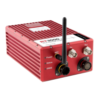
Table 19. Power or Pwr LED states
Colour Description
Off There is no power to the system or the system power supply has failed.
Green The 5 V power supply for the system is active.
Orange The system is outputting data on connector J2.
Co-ordinate frame conventions
Measurements made by the INS are available in a number of different reference frames
for use in different applications.
IMU frame
The IMU reference frame used by the RT (shown in Figure 6), is popular with navigation
systems—where the positive X-axis points forwards, the positive Y-axis points right and
the positive Z-axis points down.
When making measurements required in the configuration files, measurements should
be made between the point of interest and the measurement origin shown in Figure 6.
The axes and measurement origin point are the same for all RT models.