7.5.4 Connection Example of PC(PLC) Link
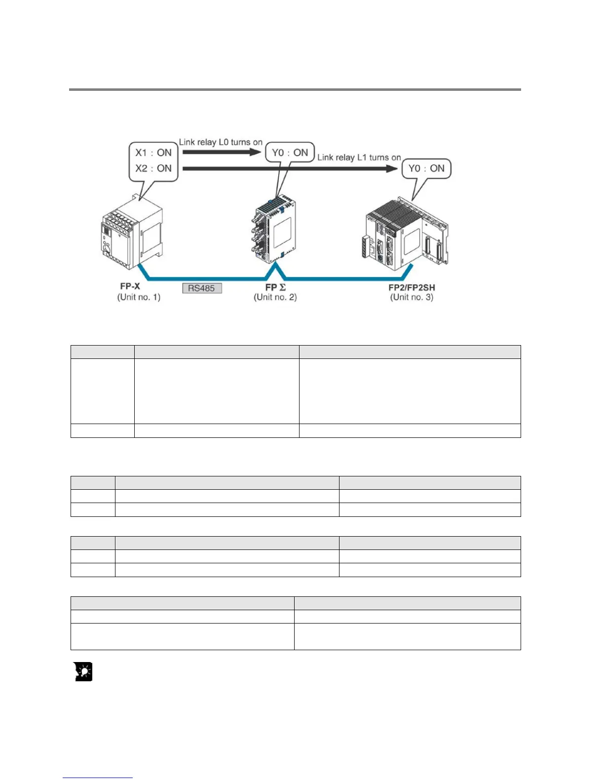
When using three PLCs
In the example shown here, link relays are use. When X1 of PLC with unit no. 1 turns on, Y0 of PLC with
unit no. 2 turns on. When X2 of PLC with unit no. 1 turns on, Y0 of PLC with unit no. 3 turns on.
System register settings
When using a PC(PLC) link, the communication format and baud rate are fixed.
No. 413 Communication format for COM1
port
Data length: ……
Parity check: …..
Stop bit: …………
Terminator: ……..
Baud rate setting for COM1 port
Unit no. and communication mode settings
- Setting for the FP-X with unit no. 1
No. 412 Selection of communication mode for COM1 port PC link
- Setting for the FP
Σ with unit no. 2
Selection of communication mode for COM1 port
- Setting for the FP2-MCU with unit no. 3
Unit no. for COM1 port 3 (Set using the unit no. setting switch)
Selection of communication mode for COM1 port PC(PLC) link
(Set using the mode speed setting switch)
Key Point:
Make sure the same unit number is not used for more than one of the PLCs connected through the
PC(PLC) link function, and specify consecutive numbers.
Phone: 800.894.0412 - Fax: 888.723.4773 - Web: www.clrwtr.com - Email: info@clrwtr.com
 Loading...