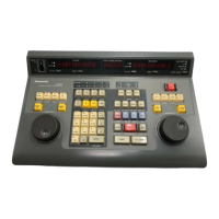
Connection method
Connect each channel as mentioned below. After the connection, confirm that the polarity and terminal
positions are correctly connected.
Note1) When extending the lead wire of RTD, use 3 wires in the same resistance and the same length.
Note2) Do not place the input signal line close to an AC power line or high-voltage line. Also, do not
bundle it with them.
Note3) Use shielded wires for the input signal line. It is recommended to ground them.
However, depending on the conditions of the external noise, it may be better not to ground the
shielding.
Noter4) Do not connect one RTD to other equipment in parallel (input).
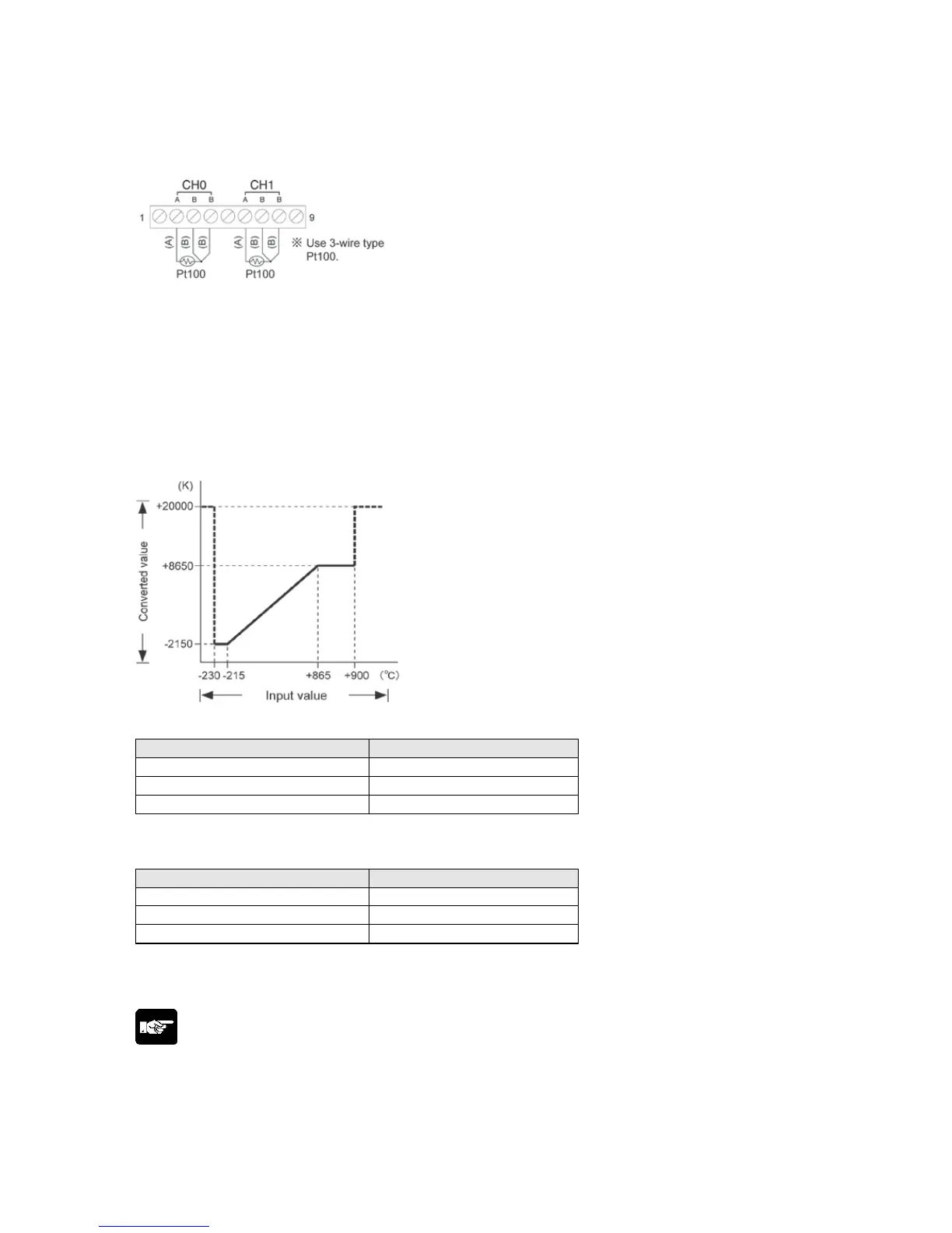
RTD input range
Conversion characteristics graph
Table of converted values
When exceeding the rated range
(Reference values which accuracy is not assured are indicated up to ±15 °C.)
Note) When exceeding the maximum/minimum value (exceeding the rated range), the converted values
will be the values as mentioned above. However, if the temperature drops (below -230 °C) or rise (over
900 °C) more, the data will be the same value (+20000) as the one at the time of disconnection.
Note:
About RTD input range
- From the Power-on to the converted data Ready (approx. 3 seconds), the digital value will be K20001.
Take care of the use of the data during this period not to influence other programs.
- From the disconnection or exceeding the rated range (digital value: K20000) to the recovery and
converted data Ready (approx. 3 seconds), the digital value will be K20001.
Take care of the use of the data during this period not to influence other programs.
Phone: 800.894.0412 - Fax: 888.723.4773 - Web: www.clrwtr.com - Email: info@clrwtr.com
 Loading...