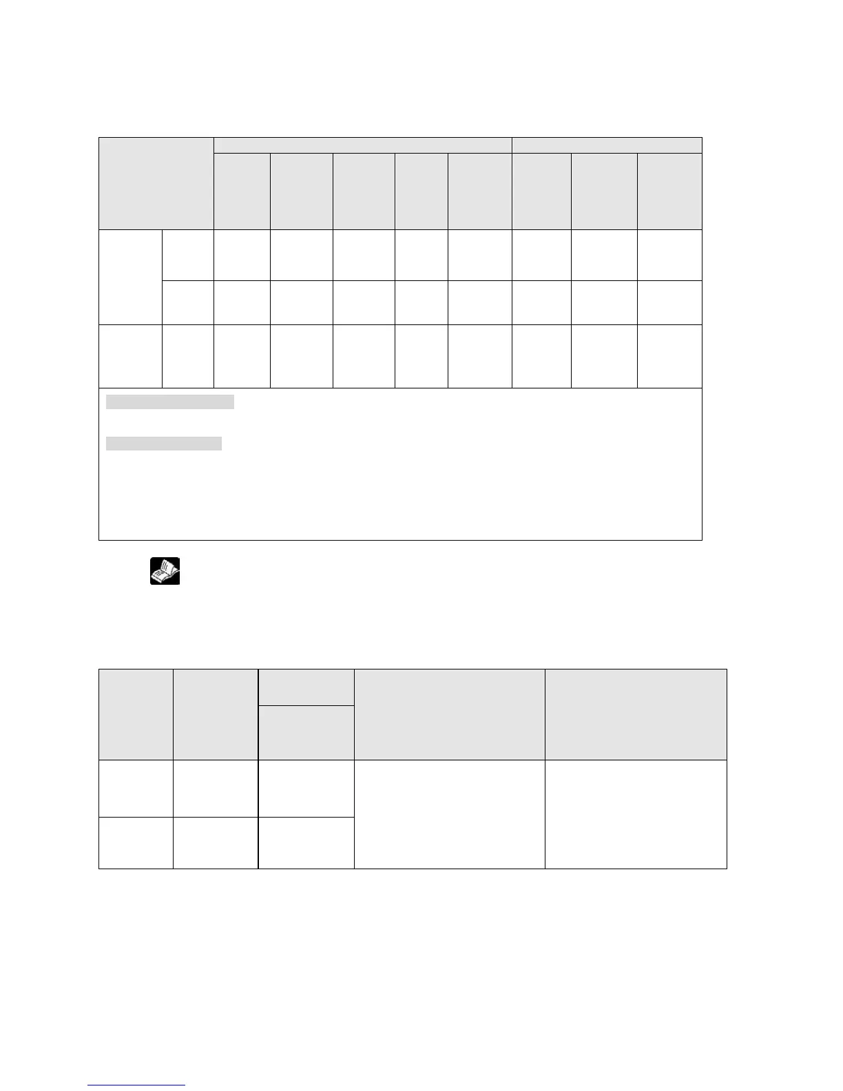
Home
input
Near
home
input
Note3)
Control
flag
Elapsed
value
area
Target
value
area
Indepen-
dence
CH0 Y100 Y101 Y102 X102
DT90052
<bit4>
R911C
DT90348
DT90349
DT90350
DT90351
CH1 Y200 Y201 Y202 X202
DT90052
<bit4>
R911D
DT90352
DT90353
DT90354
DT90355
Inter-
polation
Linear
Y100
Y200
Y101
Y201
Y102
Y202
Note1)
X102
X202
Note1)
DT90052
<bit4>
R911C
R911D
DT90348
DT90349
DT90352
DT90353
DT90350
DT90351
DT90354
DT90355
Max. output frequency
Note3)
- Using one ch: Max. 100 kHz
- Using two chs: Max. 80 kHz
Related instructions
F0 (MV) :high-speed counter control
F1 (DMV) :Read/write of elapsed value of high-speed counter
F171 (SPDH) :trapezoidal control/home return
F172 (PLSH) :JOG operation
F174 (SP0H) :Data table control
F175 (SPSH) :Linear interpolation control
Note1) The home return operation of the interpolation axes should be performed for every channel.
Note2)
Reference: For DT90052, see <10.4.4 Pulse Output Control Instruction (F0) (F1)>.
Note3) When using the AFPX-PLS only
PWM output function
PWM output when using pulse I/O cassette (AFPX-PLS)
High-
speed
counter
channel
No.
Output
contact No.
used
Memory area
used
Output frequency
(duty)
Related instructions
Control flag
CH0 Y100 R911C
-When resolution = 1000,
1.5 Hz to 12.5 kHz
(0.0 to 99.9%)
-When resolution = 100,
15.6 kHz to 41.7 kHz
(0 to 99%)
F0(MV) (High-speed counter
control)
F1(DMV) (Read/write of
elapsed value of high-speed
counter)
F173(PWMH) (PWM output)
CH1 Y200 R911D
 Loading...