272
JAN 2006
Ver. 5.2
DP-3510/3520/3530/4510/4520/4530/6010/6020/6030
Guide 1 (815) is rotated clockwise by the Selection Solenoid (621) guiding the original to the Exit Roller
(814). For double-side scanning, the Selection Guide 1 (815) is rotated counter-clockwise by the
Selection Solenoid (621) guiding the original to the Inverting Roller (809). The Selection Guide 1 (815)
moves only once, in the direction according to whether a single or double-side scanning is selected
(Copier or Fax) before the Start button is pressed.
It will remain in this position until a different operation is performed (i.e. if the last operation was 2-sided
scanning, a single-side scanning is performed).
2. Scanning the Front and the Back Side of an Original
The scanning of the Front and Back side of a 2-sided original is accomplished by means of the
Selection Guide 1 (815) and Selection Guide 2 (713).
After the Front side of the original is scanned, the original is transported through the Selection Guide 1
(815), through the Selection Guide 2 (713) that was rotated counter-clockwise by the Selection
Solenoid (621) and is carried beyond the Inverting Roller (809) and upper Pinch Rollers (626) into the
Sub Tray. The original is carried for a specified period of time after the trailing edge of the original
triggers the Selection Sensor (401) and stops within 10 to 20 mm from exiting the rollers. Then, the
Selection Guide 2 (713) is rotated clockwise by the Pinch Roller Solenoid Assembly (615) and the
reverse rotation of the ADF Motor 1 (925) pulls the original back around the Registration Roller 1 (817)
and proceeds to scan the Back side of the original.
3. Eject by Reverse Rotation
After the Back is scanned, the original is transported through the Selection Guide 1 (815), through the
Selection Guide 2 (713) and is carried beyond the Inverting Roller (809) and lower Pinch Rollers (626),
into the Sub Tray (416), again stopping 10 to 20 mm from exiting the rollers.
The Selection Guide 2 (713) is rotated clockwise by the Pinch Roller Solenoid Assembly (621) and the
reverse rotation of the ADF Motor 1 (925) pulls the original back around the Registration Roller 1 (817),
however, this time the original is routed to the Exit Roller (814) and exits into the ADF Base.
4. Sub Tray
The Inverting ADF system includes a Sub Tray (416), which supports the originals during the ejection
mode of the double-side scanning operation.
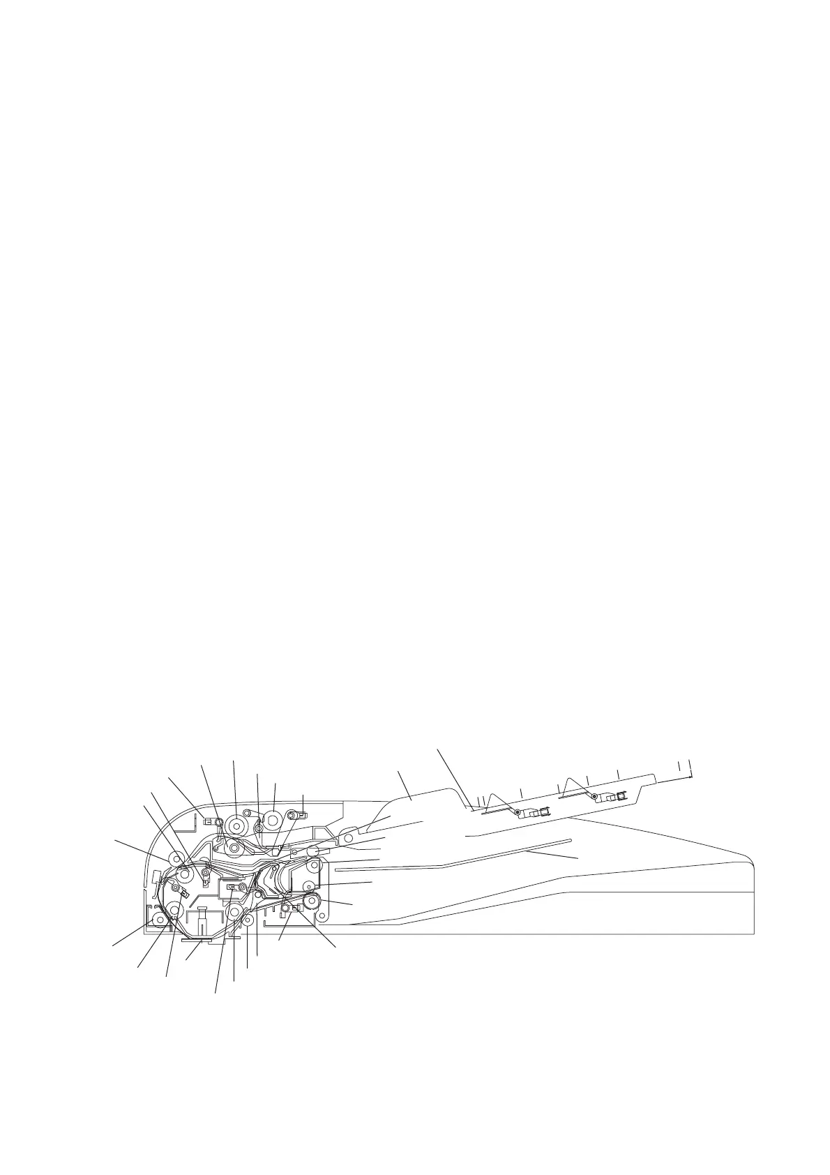
Inverting Automatic Document Feeder (i-ADF)
210 mm (A5)
215.9 mm (INVOICE)
257 mm (B5-R)
297 mm (A4-R)
330.2 mm (FLS1.2)
364 mm (B4)
420 mm (A3)
431.8 mm (Ledge
Sub Tray
Inverting Roller
Read Point
Paper Feed Roller
Pick Up Roller
Separation
Roller
Exit Roller
Transport Roller
nti Drive Registration Roller
Pinch Roller)
Anti Drive Exit Roller
(Pinch Roller)
Anti Drive Transport Roller (Pinch Roller)
Anti Drive Registration
Roller 2 (Pinch Roller)
Registration Roller 2
Registration Roller 1
Registration Sensor 3
Registration Sensor 2
Registration Sensor 1
Original Stopper
Original Detection Sensor
Original Guide
Original Tray
Selection Guide 2
Selection Sensor
Selection Guide 1
Exit Sensor
Inverting Guide Sheet
Anti Drive Exit Roller
(Pinch Roller)

 Loading...


