285
JAN 2006
Ver. 5.2
DP-3510/3520/3530/4510/4520/4530/6010/6020/6030
7.3. Installation Procedure
Note:
1. Refer to each individual Installation Instructions when installing Stands or other Optional Kits.
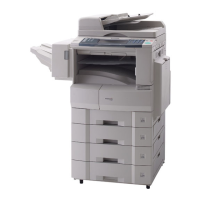
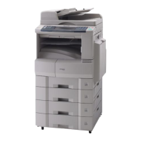
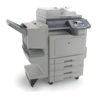
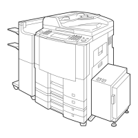
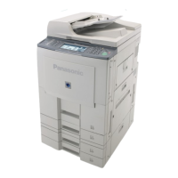
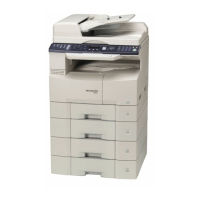
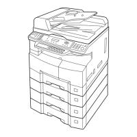
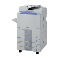
2. The following machine illustrations, depicts a DP-6030 with a standard configuration.
3. The scanner is held in place by a Shipping Blue Screw to prevent damage during transit.
Do Not turn the Power Switches ON before unlocking the scanner.
4. The machine is shipped from the factory with the Pressure Roller / OPC Drum locked in the opened
position to avoid the possibility of damaging the Pressure Rollers / OPC Drum.
Do Not turn the Power Switches ON before unlocking the Pressure Roller / OPC Drum.
7.3.1. Installation Procedure
(1) Open the 4 Handle Covers and swing the
Handles upward then pullout to lock them in
place.
Note:
To release the Handles, lift the Release Latch
upwards and push the Handles toward the
machine.
(2) Lift and place the machine on a suitable
Stand / Console, aligning with 3 Guide-Pins.
Stand (USA/Canada only)
DA-D351 / D352 : DP-3510/3520/3530/
4510/4520/4530/6010/
6020/6030
System Console
DA-DS601 / DS602 : DP-3510/3520/4510/
4520/6010/6020
DA-DS603 / DS604 : DP-3530/4530/6030
(3) Remove Tape.
(4) Remove 1 Blue Screw to unlock the Scanner.
Release
Latch
(3)
(4)
 Loading...

