Ɣ RS-485 1-to-N connection
Select “RS-485 multi” for COM setting connection mode.
Set the prefix with no duplication.
Terminator
OFF
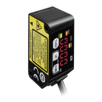
HL-G1
Area:01
HL-G1
Area:02
HL-G1
Area:16
(Green)
transmission data:+SD
+SD -SD +RD -RD
SG
(Sky Blue)
transmission data:-SD
(Orange)
reception data:+RD
(Yellow)
reception data:-RD
(Shield)
signal ground:SG(Note 2)
(Shield)
signal ground:SG(Note 2)
erminator
OFF
Terminator
ON(Note 5)
(Green)
transmission data:+SD
(Sky Blue)
transmission data:-SD
(Orange)
reception data:+RD
(Yellow)
reception data:-RD
(Shield)
signal ground:SG(Note 2)
(Green)
transmission data:+SD
(Sky Blue)
transmission data:-SD
(Orange)
reception data:+RD
(Yellow)
reception data:-RD
RS-485 host device
(Note 7)
㻌
㻌
(Note 1) The transmission data cable and reception data cable are both
twisted-pair cables.
(Note 2) The shield is connected to the 0-V side of the power supply line inside
the sensor.
(Note 3)
㻌
Be sure to connect the signal ground.
(Note 4)
㻌
The sensor is of non-isolated type. Make sure that the potential difference
between the sensor and RS-485 connecting device does not exceed 4V. A
difference in potential in excess may cause the connecting device or the sensor to
malfunction.
(Note 5) The sensor has a built-in terminating resistor. Be sure to turn ON the
terminating resistor of the terminating sensor.
(Note 6) Perform transition wiring for the transmission path.
Ramco Innovations
800
280-6933 www.panasonicsensors.com nsales
ramcoi.com

 Loading...

