Shield
Motor Ground
Phase C
Phase B
Phase A
V Bus -
Regen Resistor
V Bus+
DANGER
HIGH VOLTAGE
123456781234567812345678
DANGER
L1
L2
Earth
Earth
Earth
Control L1
Control L2
HIGH VOLTAGE
OFF
18
SW1
18
SW2
18
SW3
DIP Switch Settings
for APEX & SM Series
Motors.
see pages 6-9
MT±
Color Code:
APEX & SM
Resolver
Cables
Short MT+ to MT– if the motor
has no temperature sensor
pg 41
Resolver: Resolution is 4096 counts/rev
Flt Relay± Relay type: Normally Open
Max Current: 5A at 24VDC or
5A at 120VAC
see page 42 for more info
see
Motor Braking
on pg 42-44
RESOLVER CONNECTOR
DRIVE AUXILIARY CONNECTOR
1024 counts, pre-quadrature
Ch A leads Ch B
Ch Z pulse width is 90°
pg 37, 38
4096 counts, post-quadrature
Counts/Rev:
CW Rotation:
Ch Z:
ENCODER OUTPUT
Enable Indicates drive is enabled.
Disable Indicates drive is disabled.
Over Voltage Bus voltage exceeded 420VDC.
Regen Fault Drive faulted–excessive regen.
Regen Active Regeneration resistor on, and
dissipating excess power.
I
2
T Limit I
2
t Limit exceeded. Drive is in
foldback. Output limited to
continuous current setting.
Drive Fault Control board overtemp.
Undervoltage (brownout).
Motor Fault Resolver not connected.
Motor overtemperature.
Motor thermostat not
connected.
Bridge Fault Power stage overtemp.
Power stage overcurrent.
Motor short circuit.
Name Description/Problem
pg 60
LEDs
PROGRAMMABLE I/O
I/O Number
Input #16
Input #15
Input #14
Input #13
Input #12
Input #11
Input #10
Input #9
Output #8
Output #7
Output #6
Output #5
Pin
1
3
5
7
9
11
13
15
17
19
21
23
I/O NumberPin
Input #8
Input #7
Input #6
Input #5
Output #4
Output #3
Output #2
Output #1
Input #4
Input #3
Input #2
Input #1
25
27
29
31
33
35
37
39
41
43
45
47
49 +5VDC
Even numbered pins connect to ISO GND.
I/O are optically isolated**; HCMOS compat-
ible.* Plug is compatible with OPTO-22.
INPUTS: Connect internal 6.8KΩ pull-ups
through In-P to +5V or 0–24V supply.
OUTPUTS: Open-collector outputs. Con-
nect internal 4.7KΩ pull-ups through Out-P
to +5V or 0 – 24V supply.
COM 1
Set-up: 9600 baud, 8 data bits,1 stop bit,
no parity, full duplex.
pages 25
AUXILIARY
Name Description
ANI+ Analog Input. Not applicable.
ANI–
TRG-A Input #17. Optically isolated. In-
ternal 6.8 KΩ pull-ups through
AUX-P to 5V or external 0–24V.
see pg 28
. Use for position
capture input (INFNC).
TRG-B General purpose input #18.
Otherwise same as Trg-A.
OUT-A Output #9. Use for output on
position (OUTFNC). Circuit iden-
tical to prog. outputs.
pg 28
+5V Connect to OUT-P, IN-P, and/or
AUX-P to power I/O. 100mA
limit.
see pg 27, 28, 30, 31
OUT-P Pull-up resistors for prog.outputs
and OUT-A.
pg 29, 31
IN-P Pull-up resistors for programma-
ble inputs.
pg 29, 31
AUX-P Pull-up resistors for Home, Neg,
Pos, Trg-A/B.
pg 27, 28, 30
Connect V_I/O, Out-P, In-P, Aux-P to +5V for
HCMOS compatability.* Connect to 0 – 24V
supply for other compatibility.
pg 5, 6, 27-31
Iso GND Isolated ground.
see pg 18,19
EXTERNAL ENCODER INPUT
Optically isolated. Encoder must be: Incre-
mental; 2-ph. quadrature;differential (recom-
mended) or single-ended; HCMOS com-
patible*; Max. freq.=1.2MHz; Min. between
transitions = 833 ns.
see page 26
COM 2
Connections – see pages 25 & 32
Configuring for RS-485 – see page 10
LIMITS
Home, Pos, Neg: V_I/O sets switching volt-
age levels; internal 6.8 KΩ pull-ups through
AUX-P to 5V or ext. 0–24V supp.
see pg 27
See I/O Device Interface – pages 29-31
*HCMOS-compatibility: Low
≤
1.0V, High
≥
3.25V
**Optical isolation between I/O GND and internal
microprocessor ground, but not between inputs and outputs.
RESET
ENABLE IN
FAULT OUT
±15V
GND
TACH OUT
Active Low, ≤1.0V
pg 34, 62
Active Low, ≤1.0V
pg 35, 63
Active HIGH (floats if faulted)
(Output is held low if no fault)
page 35
15 mA at ±15V
page 36
Internally isolated from EARTH
terminal.
see pages 18,19
1V/1000 rpm for 1-speed re-
solver. Scale by DIP SW3-#5
page 36, 70
MOTOR CONNECTOR
(Underneath unit)
See pages 45
Motor Cable
Color Codes
APEX SM
TROUBLESHOOTING TIPS
TO ALLOW MOTION:
– Power must be on. (Is at least one LED on?)
– ENABLE IN must be grounded.
– Connect (or disable) limits. LH (LHØ) command.
– Set (or disable) position error. SMPER (SMPERØ)
– Set reasonable gains for system. (
see Tuning
)
– Check encoder (TPE); increments for CW move?
– Check A, V, D. (If D = Ø, no motion will occur.)
PROBLEM REPORT: TAS command reports prob-
lems. TFS command reports Following status.
INPUTS or OUTPUTS not working:
Programmable input (INFNC) functions and drive
fault detection will not operate until you enable
input functions with the INFEN1 command.
EXAMINE LEDs for indication of problem.
pg 60
•
•
•
•
Programmable output (OUTFNC) functions will not
operate unless enabled with OUTFEN1 command.
see page 69
1 volt = 2 amps commanded torque
TEST POINT
APEX6151
Compumotor
Offset
Balance
Tach Output
Calibration
Torque Cmd
Test Point
Enable
Disable
Bridge Fault
Drive Fault
Motor Fault
Over Voltage
I
2
T Limit
Regen Fault
Regen Active
Reset
Gnd
NC
Enable In
Fault Out
Gnd
NC
NC-
Tach Out
Gnd
+15V
Gnd
-15V
CHA+
CHA -
CHB+
CHB -
CHZ+
CHZ -
Gnd
Shield
Red
Blk
Grn
Blu
Brn
Wht
M T +
M T -
Flt Relay+
Flt Relay -
NC
NC
Encoder Output
ANI+
ANI -
Trg-A
Trg-B
Out-A
Iso Gnd
+5V
Out-P
In-P
Aux-P
V_I/O
Auxiliary
Iso Gnd
Home
Neg
Pos
Limits
Shield
Iso Gnd
Z -
Z+
B -
B+
A -
A+
+5V
External Encoder Input
+5V
Rx
Tx
Shld
COM 2
Rx
Tx
Iso Gnd
COM 1
Programmable Inputs/Outputs
12
5049
Ref Sin Cos
L1
L2
Earth
Earth
Earth
Control L1
Control L2
DIP Switches and
AC Input Connector
top of drive
AC INPUT
85–252 VAC;
47–66 Hz; 1-phase;
L1/L2 for high-power
amplifier,
Control L1/Control L2
for control logic.
see pg 22-24
Shield
Motor Ground
Phase C
Phase B
Phase A
V Bus -
Regen Resistor
V Bus+
Green Green/Yellow
Gray Black/Yellow
Blue White/Yellow
Orange Red/Yellow
APEX603
123456781234567812345678
SW 1
18SW 218SW 318OFF
APEX602
123456781234567812345678
SW 1
18SW 218SW 318OFF
SM231A
123456781234567812345678
SW 1
18SW 218
1234567812345678
SW 1
18SW 218
SW 318OFF
SM232A
12345678
SW 3
18OFF
SM233B
123456781234567812345678
SW 1
18SW 218SW 318OFF
Shield
Stator 3
Stator 1
Stator 2
Stator 4
Rotor 1
Rotor 2
Motor Temp+
Motor Temp–
------
Red
Black
Green
Blue
Brown
White
Yellow
Orange
Function APEX
------
Red
Black
Green
Blue
Brown
White
Yellow
Yellow
SM
Ref Sin Cos
Iso
Gnd
RX+
Rx-
Tx+
Tx-
Iso Gnd
, 29
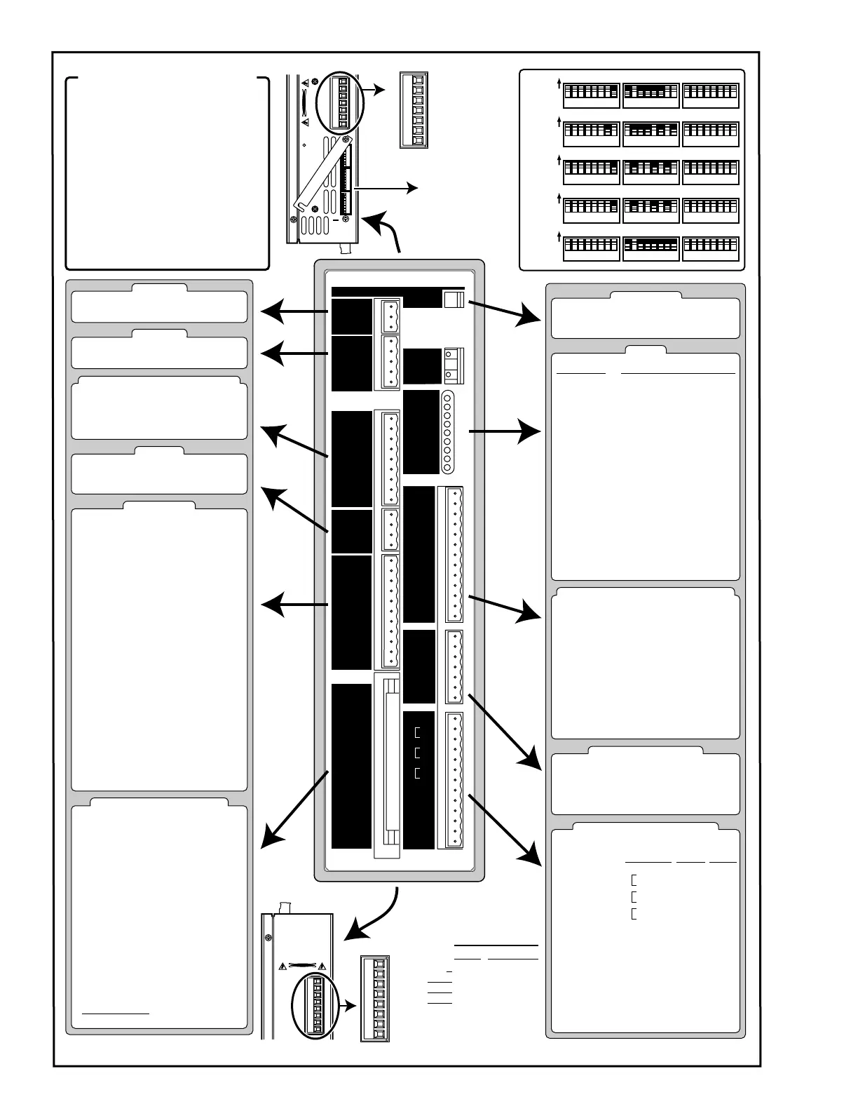
APEX6151 Servo Controller/Drive Quick Reference
See Reverse for APEX6152 & APEX6154 Quick Reference
Artisan Technology Group - Quality Instrumentation ... Guaranteed | (888) 88-SOURCE | www.artisantg.com
 Loading...


