11
Connectors motherboard CIB1
Motherboard CIB1 is the PCB interface for connections of the output cables to the VM or for connection to inner
connectors.
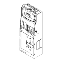
The motherboard is fixed on the housing wall (Fig.7)
MOTHERBOARD CIB1
Fig.7
J2 J3 J4
J5 J6
J8
J7
J9
J10
JP2
J1
J12
2
3
Connectors
J1 Flat cable motherboard MCB1 coin selector
J2 AC/DC Vin 24V nom.
J3 Serial EXE, BDV to VM
J4 Serial peripheral MDB
J5 Serial MDB Slave to VM
J6 Bill validator in parallel mode
J7 nc
J8 nc
J9 Paytec key reader
J10 External IrDA
J12 Flat cable motor motherboard CECB1
Fig.7A
Connectors CIB1
This jumper permits to switch the function of connector J6-pin7.
Position 3-2: signal INHIBIT on pin7.
Position 1-2: UVcc = 34V DC (nom.) on pin7.
UVcc depends on the power supplied by the VM (e.g. by an input voltage of 24VAC on J6-pin7, you have a rectified
and filtered voltage of about 34VDC (UVcc)).
Here below the diagram of the signals for connector J6 and jumper JP2.
 Loading...