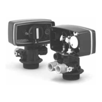
Installer Manual Fleck 5800 - SXT - Installation
Ref. MKT-IM-004 / A - 18.04.2017 37 / 92
5.3.2. Water
• Water temperature must not exceed 43°C.
• A minimum of 1.4 bar (dynamic pressure on injector) of water pressure is required for the
regeneration valve to operate effectively.
Mandatory
Do not exceed a maximum of 8.6 bar inlet pressure. Should this happen or be subject to
happen, it is necessary to install a pressure regulator upstream the system.
5.3.3. Electrical
There are no user-serviceable parts in the AC/DC adapter, motor, or controller. In the event of a
failure, these should be replaced.
• All electrical connections must be completed according to local codes.
•Use only the power AC/DC adapter that is supplied.
Mandatory
The use of any other power adapter than the one supplied void the warranty of all electronic
parts of the valve.
• The power outlet must be grounded.
• To disconnect power, unplug the AC/DC adapter from its power source.
• An uninterrupted current supply is required. Please make sure that the voltage supply is
compatible with the unit before installation.
• Make sure the controller power source is plugged in.
• If the electrical cable is damaged, it must imperatively be replaced by qualified personnel.
5.3.4. Mechanical
• Do not use petroleum-based lubricants such as vaseline, oils, or hydrocarbon-based lubricants.
Use only 100% silicone lubricants.
• All plastic connections should be hand tightened. PTFE (plumber’s tape) may be used on
connections that do not use an O-ring seal. Do not use pliers or pipe wrenches.
• Existing plumbing should be in a good shape and free from limescale. In case of doubt, it is
preferable to replace it.
• All plumbing must be completed according to local codes and installed without tension or
bending stresses.
• Soldering near the drain line should be done before connecting the drain line to the valve.
Excessive heat will cause interior damage to the valve.
• Do not use lead-based solder for sweat solder connections.
• The riser tube should be cut 5.7 mm below the top of the tank. Slightly bevel the ridge in order to
avoid deterioration of the seal whilst fitting the valve.
• The drain line must be a minimum of 12.7 mm (½") in diameter. Use 19 mm (¾") pipe if the
backwash flow rate is greater than 26.5 lpm (7 gpm) or the pipe length is greater than 6 m
(19 ft 8 in).
• Do not support the weight of the system on the valve fittings, plumbing, or the bypass.

 Loading...