25
2.8
7
11
9 12
2/2.5
7.1
2.1
7.1
7
3
SKYDECK Panel Slab Formwork
Instructions for Assembly and Use – Standard Configuration
A5 Compensations
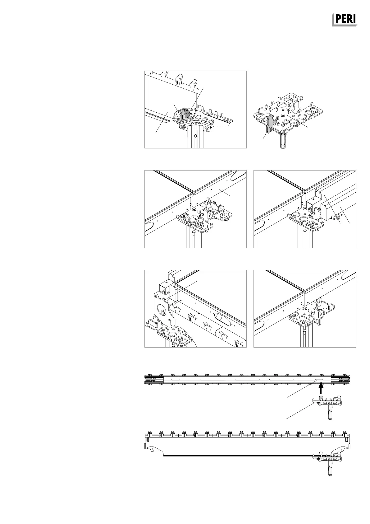
Combihead SCK
Use of longitudinal and transverse infills
up to 25 cm.
The cantilever of the Head Plate is in
longitudinal direction ≤ 19 cm, in trans-
verse direction ≤ 12.5 cm.
The Combihead (7) (Fig. A5.11) is a se-
cure, non-movable and non-twisting
support for:
– Main Beam SLT 225 (2).
– SLT 150 (2.5). (Fig. A5.10)
– Panel SDP (3). (Fig. A5.12)
– Edge Beam SRT (9) and Filler Timber
SPH (12) or timber provided by the
contractor with b = 3.8 – 8 cm and
h = 9.8 cm. (Fig. A5.13)
– End Support SSL (11). (Fig. A5.14)
Mounting the main beam
The Main Beam SLT must be mounted
in the middle of the beam support of
the SKYDECK Heads. The main beam
connection (2.1) encloses the main
beam support (7.1) of the head.
(Fig. A5.10)
The Combihead SCK has 2 main beam
supports and can be installed in both
directions. In infill areas, the cantilever
points towards the compensation.
Exceptions:
The cantilever points towards the main
beam
– when using the End Support,
(Fig. A5.14)
– when infill ≤ cantilever. (Fig. A5.14a)
Placing the main beam
With inset props, the cantilever of the
Combihead always points towards the
main beam.
Position the Combihead so that the
main beam support is securely posi-
tioned in the groove (2.8) of the main
beam.
(Fig. A5.15)
Fig. A5.10 Fig. A5.11
Fig. A5.13
Fig. A5.15
Fig. A5.12
Fig. A5.14 Fig. A5.14a
SKYDEKC AuV_ex_791458.indb 25 13.12.16 16:55