14
R
k
R
d
R
d
≥ E
d
E
d
F
k
≥
≥
γ
F
R
k
F
k
· γ
F
E
d
R
d
≥
≥
γ
M
SKYDECK Panel Slab Formwork
Instructions for Assembly and Use – Standard Configuration
A3 System dimensions
Notes regarding static calculations
This design information is used for the design and planning of the SKYDECK Slab Formwork System.
It covers standard configurations for slab thicknesses from 0.14 m to 1.09 m.
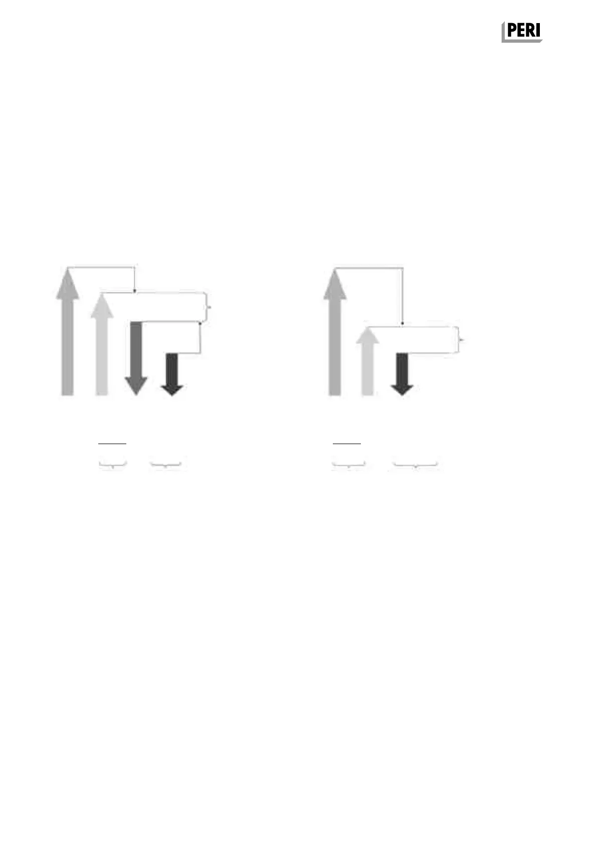
Comparison of the design method
F
ult.
(= R
k
)
F
actual
(= F
k
)
F
perm.
F
actual
(= F
k
)
F
actual
(= F
k
)F
perm.
F
ult.
γ
tot.
F
perm.
≥ F
actual
γ
tot.
The design concept with partial safety
factors
The old design concept with the
global safety factor
(see PERI Design Tables)
Method of proof Method of proof
R
k
= characteristic resistance
R
d
= design value of the resistance
F
k
= F
actual
= actual or characteristic action
E
d
= design value of the action
F
ult.
= R
k
= characteristic resistance (e.g. breaking load)
F
perm.
= permissible load-bearing capacity
γ
M
= partial safety factor for the material
(steel ≈ 1.1 / concrete ≈ 1.5)
γ
F
= partial safety factor for the load
(permanent = 1.35 / changeable = 1.5)
γ
tot.
= global safety factor ≈ γ
M
· γ
F
(steel ≈ 1.65 / concrete ≈ 2.25)
Design method used in this design
information
This design information is based on the
design concept with the global safety
factor.
The tables of the prop loads include the
permissible load-bearing capacities
F
perm.
After multiplication using γ
F
= 1.5, the
maximum load-bearing capacity can
also be converted into a design value of
the resistance R
d
for the method with
partial safety factors.
Key
SKYDEKC AuV_ex_791458.indb 14 13.12.16 16:54