61
41.1
2.8
41.1
41.1
41.2
42
41.3
43
41.3
24
41.2
α
90°
β
β
h
licht
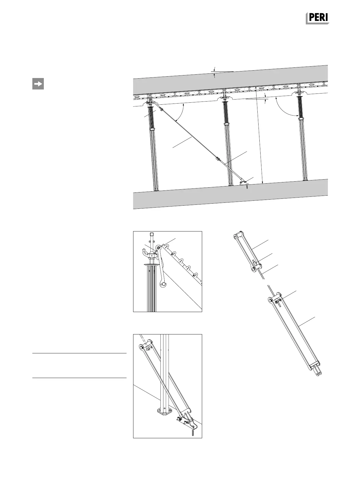
A11 Inclined slabs
Bracing with Tension Unit SD
Bracing angle α selection: see Table
A15.02.
Tension forces and prop loads: see
Tables A15.03 – A15.08.
Assembly
1. Position slab prop with tripod.
2. Place the Tension Unit Upper Part
(41.1) on the end plates of the Main
Beam SLT (2.8) and attach the Main
Beam to the Drophead SFK.
(Fig. A11.03)
3. Swivel up the Main Beam with the
second slab prop. Tension Unit must
lie on the end plates of the Main
Beam SLT.
4. Mount Base Plate (24) on a suffi-
ciently load-bearing surface area, e.g.
using PERI Anchor Bolt 14/20x130,
Item no. 124777. Take into considera-
tion the Technical Data Sheet!
5. Insert the Tie Yoke of the Tension
Unit Upper Part onto the Tie Rod
(41.3), secure with the Hex. Nut
SW30/50 (42), and attach to the
Tension Unit Upper Part.
(Fig. A11.03 + A11.04)
6. Fix Tension Unit Lower Part (41.2) to
the Base Plate by means of bolts, and
secure bolts using cotter pins.
(Fig. A11.02)
7. Insert Tie Yoke of the Tension Unit
Lower Part onto the Tie Rod, secure
with Triple Wingnut DW 15 (43), and
attach to the Tension Unit Lower Part.
(Fig. A11.05 + A11.06)
8. Tension the Tension Unit using a Triple
Wingnut.
Components
24 Base Plate RS
24.1 Anchor Bolt PERI 14/20 x 130
41 Tension Unit SD
Fig. A11.03
Fig. A11.0 6
Fig. A11.0 4
Fig. A11.05
Fig. A11.02
SKYDECK Panel Slab Formwork
Instructions for Assembly and Use – Standard Configuration
SKYDEKC AuV_ex_791458.indb 61 13.12.16 16:57