66
[cm] [kN/m
2
] [kN] [%] [°] [kN] [%] [°]
14 5.13 20.3 5.4 3.1 11.4 11.1 6.3
16 5.62 22.0 4.8 2.8 12.3 10.2 5.8
18 6.11 23.7 4.3 2.5 13.1 9.4 5.4
20 6.60 25.4 3.9 2.2 14.0 8.7 5.0
22 7.09 27.1 3.5 2.0 14.8 8.1 4.6
24 7.58 28.7 3.2 1.8 15.7 7.6 4.3
25 7.8 3 29.6 3.1 1.8 16.1 7.3 4.2
26 8.07 30.4 2.9 1.7 16.5 7.1 4.1
28 8.56 32.1 2.7 1.5 17.4 6.6 3.8
30 9.05 33.8 2.4 1.4 18.2 6.2 3.6
35 10.38 38.4 1.9 1.1 20.5 5.3 3.0
40 11.73 43.1 1.5 0.8 22.8 4.6 2.6
43 12.54 45.9 1.3 0.7 24.2 4.2 2.4
45 13.08 25.2 4.0 2.3
50 14.43 27.5 3.5 2.0
55 15.77 29.8 3.0 1.7
60 17.12 32.1 2.7 1.5
65 18.47 34.5 2.4 1.3
70 19.82 36.8 2.1 1.2
75 21.08 39.0 1.8 1.1
80 22.30 41.1 1.7 0.9
85 23.53 43.2 1.5 0.8
90 24.75 45.3 1.3 0.8
30 ° 1.72 m 2.01 m 1.73 m 2.02 m
35 ° 2.02 m 2.34 m 2.04 m 2.36 m
40 ° 2.37 m 2.71 m 2.39 m 2.73 m
45 ° 2.77 m 3.12 m 2.80 m 3.15 m
50 ° 3.25 m 3.60 m 3.28 m 3.63 m
55 ° 3.84 m 4.16 m 3.88 m 4.20 m
60 ° 4.60 m 4.87 m 4.65 m 4.91 m
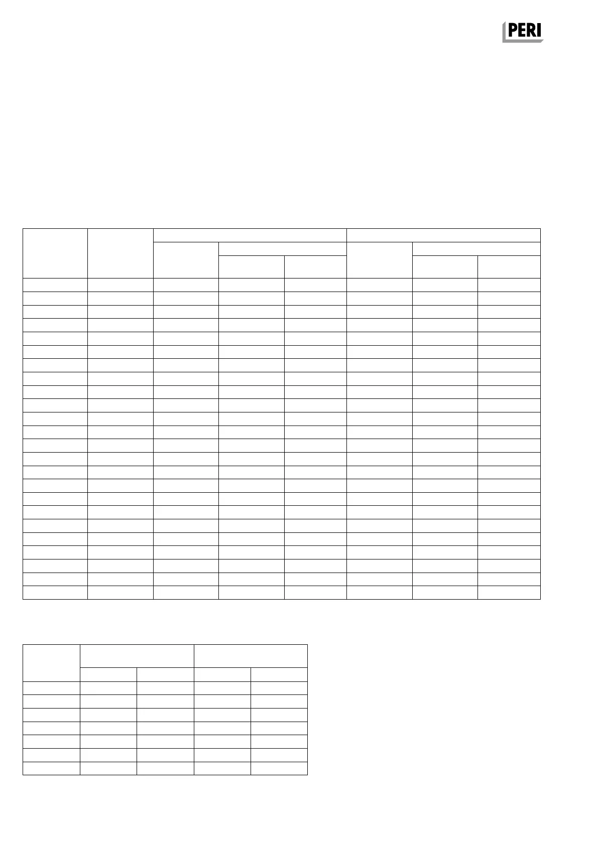
A15 Inclined slabs
Maximum permissible slab inclination with Tension Sleeve SAO and Chain 3.0 kN
Considered horizontal loads
Horizontal load from working operations = 1% of the vertical load (DIN EN 12812; 8.2.2.2)
Horizontal load from the tilting position = 1% of the vertical load (DIN EN 12812; 9.3.4.2)
Angle α between Chain and SLT 225 = 60°
Max. tension force of Tension Sleeve SAO and Anchor Chain = 3.0 kN
Panel span c = 1.50 m [cm] Panel span c = 0.75 m [cm]
max. slab inclination max. slab inclination
Slab thickness
Load
DIN EN 12812
increased prop
load Incline Angle
increased prop
load Incline Angle
Table A15.01
Table A15.02
Angle α
Tension Unit
SD
possible clear room height
with SSK and SLT 225
possible clear room height
with SFK and SLT 225
min h
minimum clearance
max h
minimum clearance
min h
minimum clearance
max h
minimum clearance
SKYDECK Tension Unit SD – bracing angle α selection
SKYDECK Panel Slab Formwork
Instructions for Assembly and Use – Standard Configuration
SKYDEKC AuV_ex_791458.indb 66 13.12.16 16:58