17
6
8
2
1
1.2
1.2
1
2.1
1375
1500
2025
250
125
2275
A
A
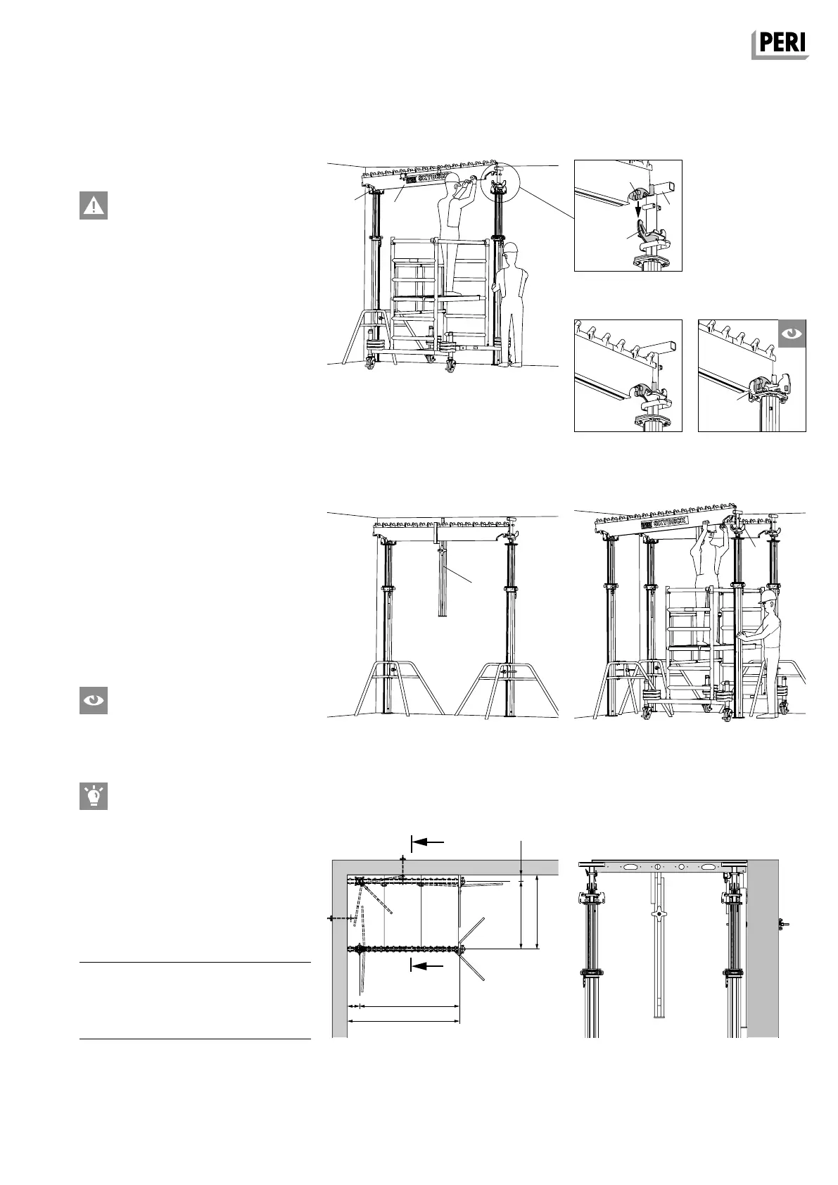
SKYDECK Panel Slab Formwork
Instructions for Assembly and Use – Standard Configuration
A4 Shuttering
Starting bay
Shuttering using a safe mobile
scaffold!
Position props and main beams
1. Position prop with Prophead (6) in
one corner of the room (spacing: see
Fig. A4.05).
2. Secure with tripod to prevent it from
falling over.
3. Position prop with Drophead (1). Dis-
tance from the wall 2.275 m.
(Fig. A4.01)
4. Secure with tripod to prevent it from
falling over.
5. Insert Main Beam SLT 225 (2) into the
beam support of the Prophead and
Drophead. The main beam connec-
tion (2.1) must be mounted in the
middle of the beam support (1.2) of
the SKYDECK heads. (Fig. A4.02a /
A4.02b / A4.02c)
6. Secure Main Beam SLT 225 (2) with
Wall Holder SWH-2 (8).
7. Position second pair of props at a dis-
tance of 1.50 m from the wall.
8. Insert Main Beam SLT 225 (2) in the
beam support. (Fig. A4.02a / A4.02b /
A4.02c / A4.04)
Does the main beam connection (2.1)
enclose the beam support (1.2)?
(Fig. A4.02c)
Set up drophead props on the wall so
that the drophead wedge can be re-
moved during striking.
The Main Beam SLT is always posi-
tioned parallel to the longer wall side.
Always check the rectangularity of the
first bay.
Components
1 Drophead SFK
2 Main Beam SLT
6 Prophead SSK
8 Wall Holder SWH-2
Fig. A4.01
Fig. A4.03
Fig. A4.02c
Fig. A4.02a
Fig. A4.04
Fig. A4.02b
Section A-A
Fig. A4.05 Fig. A4.05a
SKYDEKC AuV_ex_791458.indb 17 13.12.16 16:54