58
27
27.2
27.1
11
11
2.5
2
33a 3 3.1 9/12
30
2a
30
1
1
2
1a
B B
2
27, 11
1,50 m
1.50 m
X
16
3.1
30
2a
2a
1
2
1
1b
2
2
A
27, 11
27, 11
A
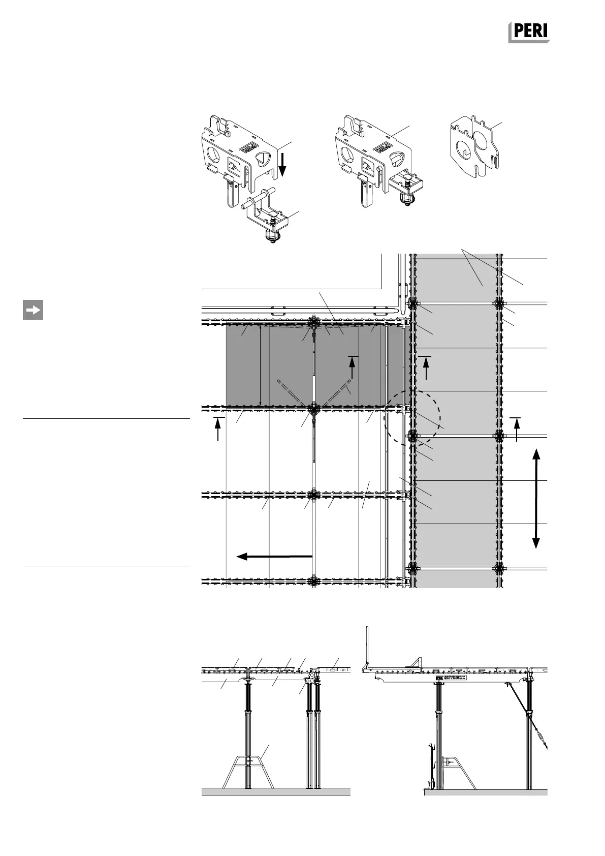
A10 Changing direction
System with Drophead SFK
If the Drophead SFK is used in the main
bay, then the Transition Head SDFK (27)
is to be used when changing direction.
It consists of a Drophead (27.1) and Con-
nector (27.2).
Changing the main bay direction by
90°
With the change in direction, the main
bays are turned 90° without having to
assemble a new system.
As a result, T- and L-shaped ground
plans are possible.
The change of direction is realized using
Main Beams SLT, additional slab props
with Transition Head SDFK in the outer
row of the main bay as well as the
Frame MRK.
Required components per change of
direction bays
1 Drophead SFK 1x
2 Main Beam SLT 225 1x
2a Main Beam SLT 150 / 225 1x
3 Panel SDP 150 x 75 1x
3.1 Panel SDP 150 x 37.5 1x
9 Edge Beam SRT 150 1x
11 End Support SSL 1x
12 Filler Timber SPH 1x
16 Filler plate 1x
27.1 Drophead SDFK* 1x
27.2 Connector SDFK* 1x
30 Tripod 1x
* Transition Head SDFK
Overview
(Fig. A10.06 + A10.06a)
Assembly of main bay direction
Assemble slab formwork in the direc-
tion of the main bay with slab props,
Drophead SFK (1), Main Beam SLT 225
(2) and Panels SDP (3): see Section A4
Shuttering.
Section A-A Change in direction in the edge bay with
Main Beam SLT 375
Fig. A10.06a
Fig. A10.06
Fig. A10.05
Main bays
Starting bay of the trans-
verse bay direction
Transverse bay
direction
Main bay direction
SKYDECK Panel Slab Formwork
Instructions for Assembly and Use – Standard Configuration
SKYDEKC AuV_ex_791458.indb 58 13.12.16 16:57