57
2
2.5
2.5
26
2.5
2
26.1
12
3
16
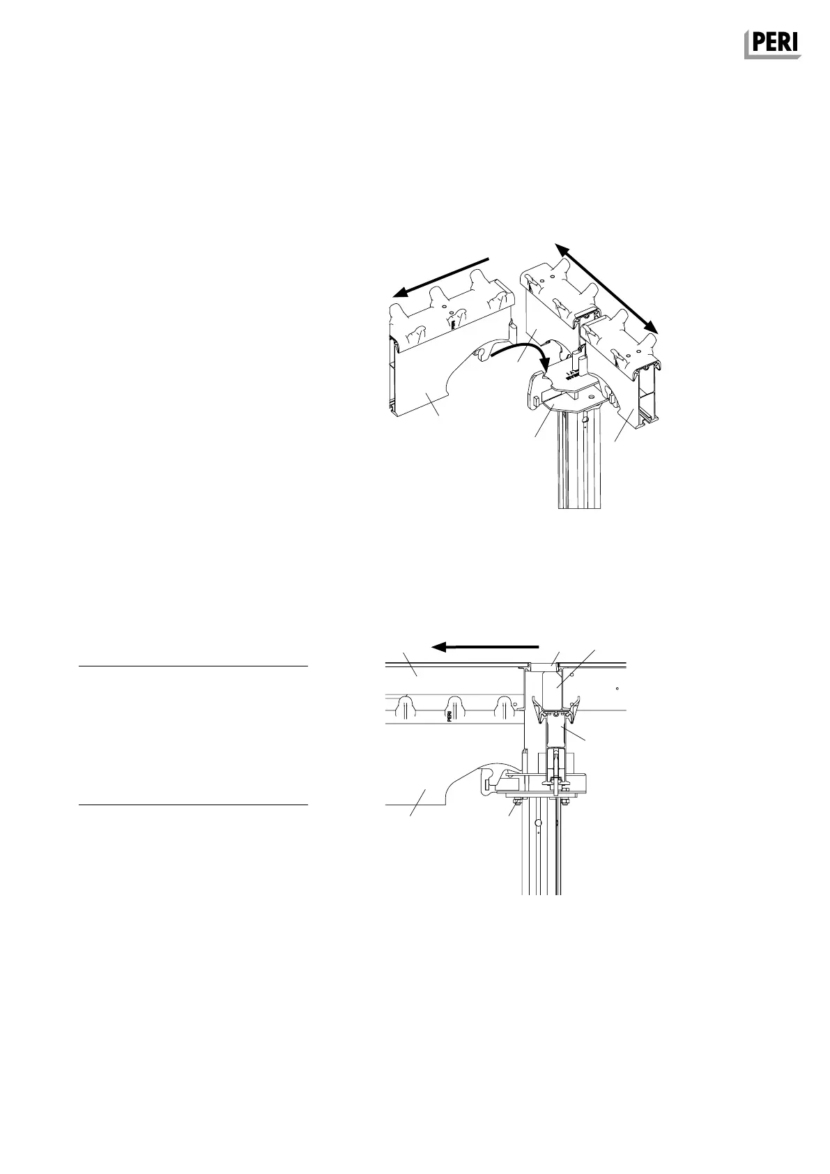
A10 Changing direction
Changing direction
Main bay direction
1. Install slab prop with Prophead SDSK
(26) with a spacing of 1.50 m and
secure with tripods.
2. Mount Main Beam SLT 150 (2.5) –
instead of SLT 225.
(Fig. A10.02 + A10.02a)
Transverse bay direction
3. Continue assembling in the direction
of the transverse bay with slab prop,
Prophead SSK (6) and Main Beams
SLT: see Section A4 Shuttering. (Fig.
A10.02 + A10.03) Secure slab props
with tripods.
4. Install Panels SDP 150 x 75 (3) in the
direction of the transverse bay.
(Fig. A10.02)
5. If a gap occurs with the Panel SDP
between the transverse bay direction
and main bay direction, this is closed
using filler timber (12) and filler plates
(16). (Fig. A10.04)
Transverse bay direction
Main bay direction
Transverse bay
direction
Fig. A10.03
Fig. A10.04
Detail X
without filler timber
Section B-B
with filler timber
Required components per change of
direction bays
26 Prophead SDSK* 1x
26.1 Bolt M12 with MP Nut 2x
6 Prophead SSK 1x
2.5 Main Beam SLT 150 1x
2 Main Beam SLT 225** 1x
3 Panel SDP** x
12 Filler Timber SPH 1x
16 Filler plate 1x
* Transition Head SDSK
** Depending on size of bay or plan
SKYDECK Panel Slab Formwork
Instructions for Assembly and Use – Standard Configuration
SKYDEKC AuV_ex_791458.indb 57 13.12.16 16:57