41
60°
0.540.540.540.540.540.540.540.54 2.447 kN
2.447
1.02 kN*
1.02 kN
1.02 kN*
2.447 kN
2.447 kN
2.447 kN
0.54 kN 0.54 kN0.54 kN
1.43 kN
1.43 kN
1.43 kN
1.43 1.43
=
1.50 kN
2.60 kN
3.00 kN
60°
SKYDECK Panel Slab Formwork
Instructions for Assembly and Use – Standard Configuration
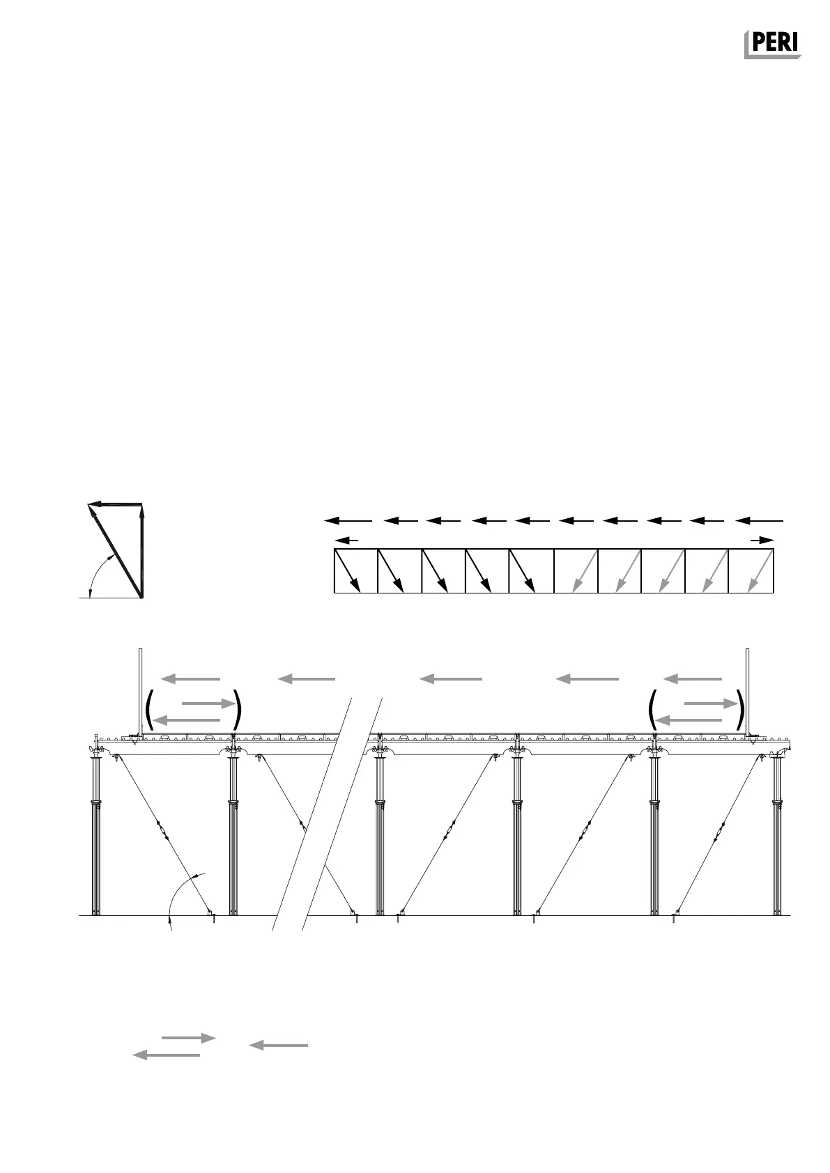
A7 Horizontal bracing
Requirements
– Load Case Combination LFK 1:
Concreting
– Load Case Combination LFK 2: Storm
– Slab thickness d = 25 cm
– Panel span = 1.50 m
– 2 edge areas
– 8 inner bays
Number of chains
– The load case combination which re-
sults in the biggest value is decisive.
– Permissible horizontal component of
the tension load on the anchor chain
= 3 kN x cos 60° = 1.5 kN. (Fig. A7.04)
Calculation
Load Compilation LFK 1 Concreting
2 x (H
load
edge area − stopendformwork pressure*)
+ (8 x H
load
inner bay) = ∑H
2 x (2.447 kN − 1.43 kN) + (8 x 0.54 kN) = 6.354 kN
Load Compilation LFK 2 Storm
2 x H
load
edge area + (8 x H
load
inner bay) = ∑H
2 x 1.291 kN + (8 x 0.033 kN) = 2.846 kN
Number of chains
∑H = 2.846 kN < 6.354 kN
LFK 1 Concreting is decisive
n
chain
= ∑H / perm. tension force of chain
= 6.54 kN : 1.5 kN = 4.236 chains = 5 chains per load direction
Example 2:
Open building edge on both sides
Bracing in both building directions. (Fig. A7.08)
Values: see Table A14.01.
Fig. A7.04
*The stopend formwork pressure is already included in Load Case Combination
LFK 1 for edge areas. Through reciprocal elimination on both sides of the
open building edge, this value must be deducted from both sides.
Chain 1 Chain 2 Chain 3 Chain 4 Chain 5
Fig. A7.07
Fig. A7.08
SKYDEKC AuV_ex_791458.indb 41 13.12.16 16:56