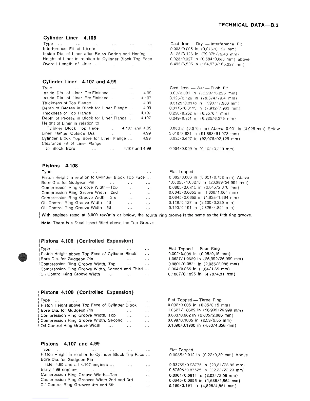
Cylinder Liner 4.108
Type
Interference
Fit
of
Liners
Inside
Dia. of
Liner
after Finish Boring and Honing
Height
of
Liner
in relation to Cylinder
Block
Top Face
Overall Length
of
Liner
Cylinder Liner 4.107 and 4.99
Type
Inside
Dia.
of
Liner
Pre-Finished
4.99
Inside
Dia.
of
Liner Pre-Finished 4.107
Thickness
of Top
Flange.
4.99
Depth of Recess in
Block
for Liner
Flange.
4.99
Thickness
of Top
Flange..
4,107
Depth of Recess in
Block
for
Liner Flange 4,107
Height
of Liner
in
relation to
Cylinder
Block
Top
Face 4,107 and 4.99
Liner
Flange Outside Dia. 4.99
Cylinder
Block
Top Bore for
Liner
Flange 4.99
Clearance Fit of
Liner
Flange
to
Block
Bore 4.107 and 4.99
Pistons 4.108
Type
Piston Height in relation to Cylinder
B!ock
Top
Face.
Bore Dia.
for
Gudgeon
Pin
Compression Ring Groove
Width-Top
Compression Ring Groove
Width-2nd
Compression Ring Groove
Width-3rd
Oil Control Ring Groove
Width-4th
Oil Control Ring Groove
Width-5th
i With
engines
rated at 3.000
rev/min
or
below,
the
fourth
Note: There is a Steel Insert fitted above the Top Groove.
I Pistons 4.108
(Controlled
Expansion)
I
IType
...
I Piston
Height
above Top Face of
Cylinder
Block
I Bore Dia.
for
Gudgeon Pin
I Compression Ring Groove Width,
Top
1 Compression Ring Groove Width,
Second
and
Third
.. .
I Oil Control Ring Groove Width
...
...
..
.
: Pistons 4.108
(Controlled
Expansion)
: Type
...
I Piston Height above Top Face
of
Cylinder
Block
:
Bore
Dia.
for
Gudgeon Pin
I CompreSSion Ring Groove Width,
Top
: Compression Ring Groove Width,
Second
I Oil Control Ring Groove Width
Pistons 4.107 and 4.99
Type
Piston Height in relation to
Cylinder
Block
Top Face ..
Bore Dia.
for
Gudgeon
Pin
later 4.99 and all 4.107
engines
...
Early 4.99
engines
Compression Ring Groove
Width-Top
Compression Ring Grooves Width 2nd and 3rd
Oil Control Ring Grooves 4th and 5th
TECHNICAL
DATA-B.3
Cast Iron - Dry -
Interference
Fit
0,003/0.005
in
(0,076/0.127
mm)
3.12513.126
in
(79,375179,40
mm)
0.023/0.027
in
(0,584/0,686
mm)
above
6.495/6.505
in
(164,973/165,227
mm)
Cast Iron - Wet Push Fit
3,00/3.001
in
(7620176.225
mm)
3.125/3,126
in
(79,374179.4
mm)
0.312510.3145
in
(7,93717,988
mm)
0.3115/0.3135
in
(7,91217,963
mm)
0.25010,252
in
(6.35/6,4
mm)
0.249/0,251
in
(6.325/6,375
mm)
0.003 in (0,076 mm) Above. 0.001
in
(0.025 mm)
Below
3.61813.621
in
(91.898/91,973
mm)
3.625/3,627
in
(92,075/92,125
mm)
0,00410.009
in
(0,102/0.229
mm)
Flat Topped
0.00210.006
in
(0,051/0.152
mm)
Above
1.06255/1.06275
in
(26,989/26.994
mm)
0.080510.0815
in
(2,045/2,070
mm)
0.0645/0.0655
in
(1,638/1,664
mm)
0.0645/0.0655
in
(1,638/1,664
mm)
0.126/0.127
in
(3.200/3,225
mm)
0.19010.191 in
(4,826/4.851
mm)
ring
groove
is
the
same as
the
fifth
ring
groove.
Flat
Topped
- Four Ring
0.002/0.006
in
(0,05/0,15
mm)
1.062711.0629
in
(26,992/26,999
mm)
0.080110.0821
in
(2,035/2,086
mm)
0.06410.065
in
(1,64/1,65
mm)
0.1887/0.1895
in (4,7914,81
mm)
Flat
Topped
-
Three
Ring
0.002/0.006
in
(0,05/0,15
mm)
1.062711.0629
in
(26,992/26,999
mm)
0.080/0.082
in
(2,035/2,086
mm)
0.09910.1005
in
(2,53/2,55
mm)
0.1890/0.1900
in
(4,8014,826
mm)
Flat
Topped
0.0085/0.012
in
(0,2210,30
mm)
Above
0.93755/0.93775
in
(23,81/23,82
mm)
0.87505/0.87525
in
(22,22122,23
mm)
0.0801/0.0811
in
(2,034/2,06
mm)
0.0645/0.0655
in
(1,638/1,664
mm)
0.190/0.191
in
(4,826/4,851
mm)