CHECKING GLOW
PLUGS
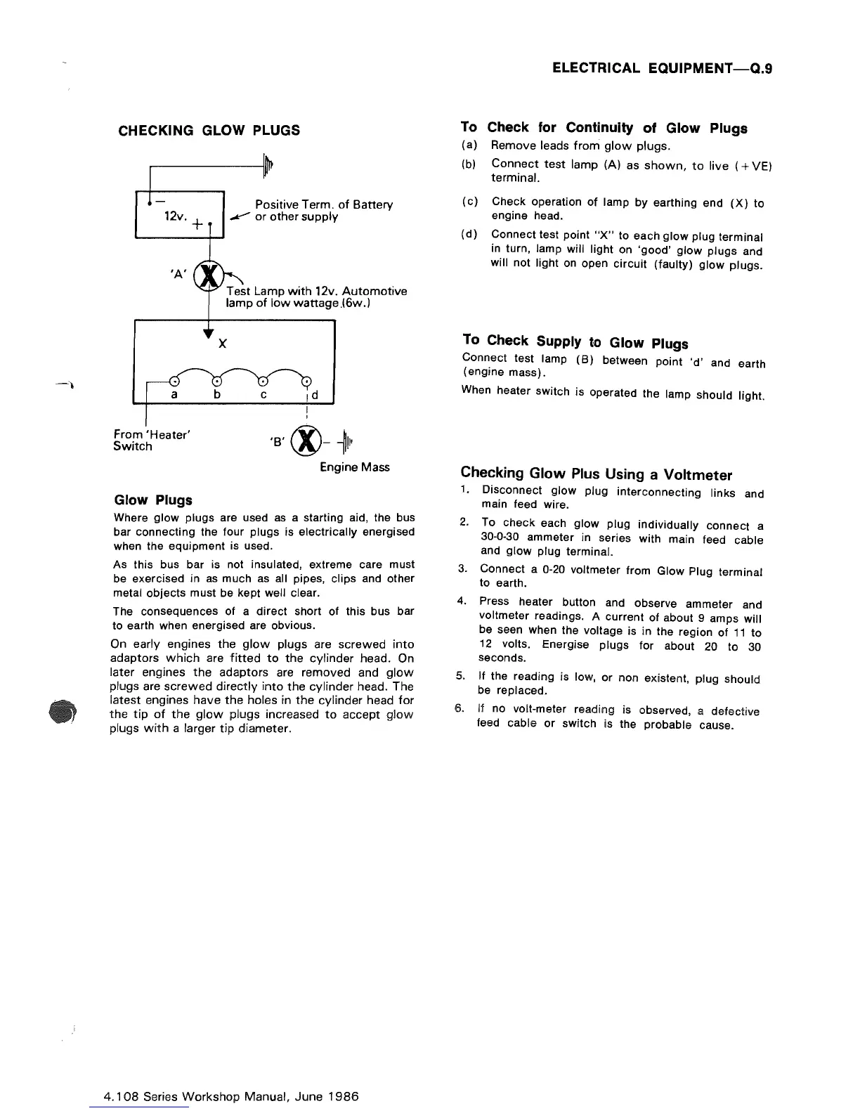
'A'
From
'Heater'
Switch
Glow
Plugs
Positive
Term.
of
Battery
.."y"
or
other
supply
Test
Lamp
with
12v.
Automotive
lamp
of
low
wattage.l6w.)
x
'B'®-~II'
Engine Mass
Where glow plugs are used
as
a starting aid, the bus
bar connecting the four plugs is electrically energised
when the equipment is used.
As this bus bar is not insulated, extreme care must
be exercised in
as
much as all pipes, clips and other
metal objects must be kept well clear.
The consequences of a direct short of this bus bar
to earth when energised are obvious.
On early engines
the
glow
plugs are
screwed
into
adaptors
which
are
fitted
to
the
cylinder
head. On
later engines
the
adaptors
are
removed
and
glow
plugs are
screwed
directly
into
the
cylinder
head. The
latest
engines
have
the
holes in
the
cylinder
head
for
the
tip
of
the
glow
plugs increased
to
accept
glow
plugs
with
a larger
tip
diameter.
4.108
Series
Workshop
Manual,
June
1986
ELECTRICAL EQUIPMENT
-Q.9
To
Check
for
Continuity of Glow Plugs
(a) Remove leads
from
glow
plugs.
(b)
Connect
test
lamp (A) as
shown,
to
live
(+
VEl
terminal.
(c)
Check operation of lamp by earthing end
(X)
to
engine head .
(d)
Connect test point
"X"
to
each glow plug terminal
in turn, lamp will light on 'good' glow plugs and
will not light on open
circuit
(faulty)
glow
plugs.
To
Check Supply
to
Glow
Plugs
Connect test lamp
(B)
between point
'd'
and earth
(engine mass).
When heater switch is operated the lamp should light.
Checking Glow
Plus
Using a Voltmeter
1.
Disconnect glow plug interconnecting links and
main feed wire.
2.
To check each glow plug individually connect a
30-0-30 ammeter in series with main feed cable
and
glow
plug terminal.
3.
Connect a
0-20
voltmeter from Glow Plug terminal
to earth.
4.
Press heater button and observe ammeter and
voltmeter readings. A current of about 9 amps will
be seen when the voltage is in the region of
11
to
12
volts. Energise plugs
for
about
20
to
30
seconds.
5.
If the reading is low,
or
non existent, plug should
be replaced.
6.
If no volt-meter reading is observed, a defective
feed cable
or
switch is the probable cause.