SECTION J
Timing Case and Drive
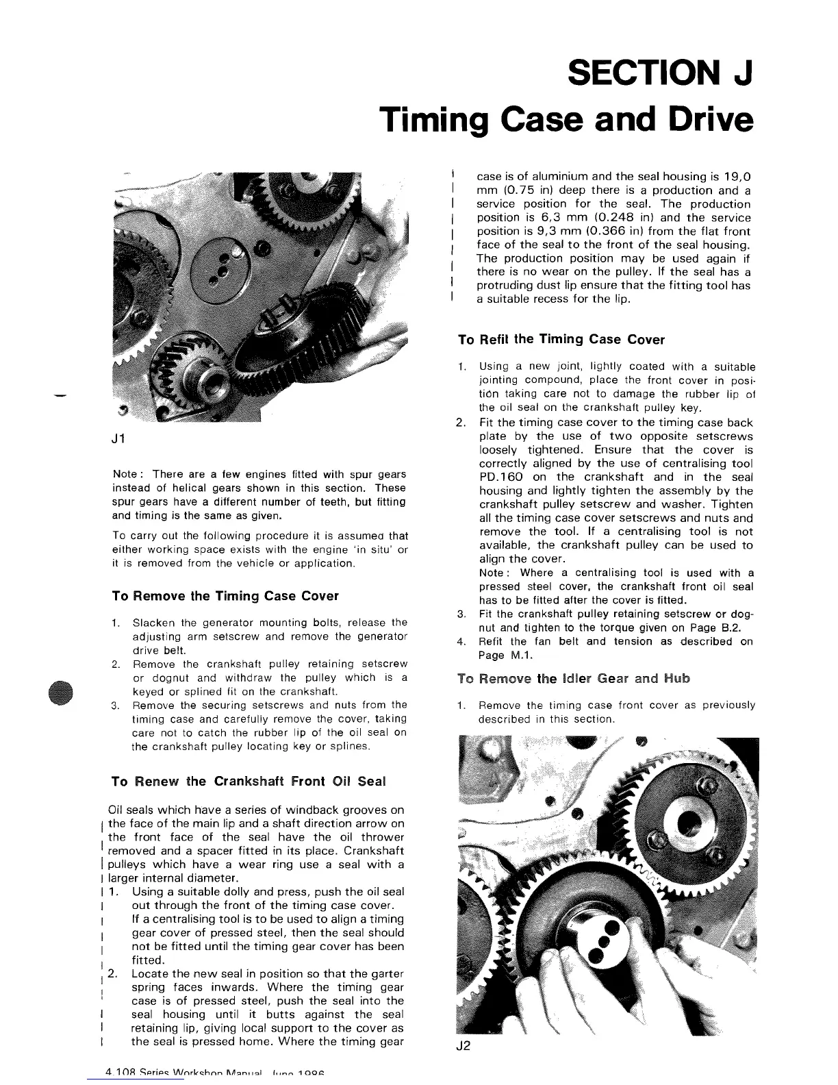
J1
Note:
There are a few engines fitted with spur gears
instead of helical gears shown in this section. These
spur gears have a different number of teeth, but fitting
and timing is the same
as
given.
To carry out the following procedure it is assumed that
either working space exists with the engine 'in situ' or
it is removed from the vehicle or application.
To Remove the Timing Case Covel'
1.
Slacken the generator mounting bolts, release the
adjusting arm setscrew and remove the generator
drive belt.
2.
Remove the crankshaft pulley retaining setscrew
or
dognut and withdraw the pulley which
is
a
keyed
or
splined fit
on
the crankshaft.
3.
Remove the securing setscrews and nuts from the
timing case and carefully remove the cover, taking
care not to catch the rubber lip of the oil seal on
the crankshaft pulley locating key or splines.
To Renew the Crankshaft
front
Oil Seal
Oil seals
which
have
a series
of
windback
grooves
on
I
the
face
of
the
main
and a
shaft
direction
arrow
on
the
front
face
of
the
seal
have
the
oil
thrower
I
removed
and a
spacer
fitted
in
its
place.
Crankshaft
I pulleys
which
have
a
wear
ring use a seal
with
a
I larger
internal
diameter.
I 1. Using a
suitable
dolly
and press,
push
the
oil seal
out
through
the
front
of
the
timing
case
cover.
If
a
centralising
tool
is
to
be used
to
align a
timing
gear
cover
of
pressed steel,
then
the
seal
should
not
be
fitted
until
the
timing
gear
cover
has been
I
fitted.
I 2.
Locate
the
new
seal in
position
so
that
the
garter
spring
faces
inwards.
Where
the
timing
gear
case is
of
pressed steel, push
the
seal
into
the
seal
housing
until
it
butts
against
the
seal
retaining lip,
giving
local
support
to
the
cover
as
case is
of
aluminium
and
the
seal
housing
is
19,0
mm
(0.75
in) deep
there
is a
production
and a
service
position
for
the
seal.
The
production
position
is
6,3
mm
(0.248
in) and
the
service
position
is
9,3
mm
(0.366
in)
from
the
flat
front
face
of
the
seal
to
the
front
of
the
seal
housing.
The
production
position
may
be
used
again
if
there
is
no
wear
on
the
pulley.
If
the
seal has a
protruding
dust
lip
ensure
that
the
fitting
tool
has
a
suitable
recess
for
the
lip.
To Refit the
Timing
Case Cover
1. Using a new joint, lightly coated with a suitable
jointing compound, place the front
cover
in posi-
tion taking care not to damage the rubber lip of
the oil seal on the crankshaft pulley key.
2. Fit
the
timing
case
cover
to
the
timing
case
back
plate
by
the
use
of
two
opposite
setscrews
loosely
tightened.
Ensure
that
the
cover
is
correctly
aligned
by
the
use
of
centralising
tool
PD.160
on
the
crankshaft
and in
the
seal
housing
and
lightly
tighten
the
assembly
by
the
crankshaft
pulley
setscrew
and
washer.
Tighten
all
the
timing
case
cover
setscrews
and
nuts
and
remove
the
tool.
If
a
centralising
tool
is
not
available,
the
crankshaft
pulley
can
be used
to
align
the
cover.
Note:
Where a centralising tool is used with a
pressed steel cover, the crankshaft front oil seal
has to be fitted after the cover is fitted.
3.
Fit the crankshaft pulley retaining setscrew
or
dog-
nut and
lighten
to the torque given on Page B.2.
4. Refit the fan belt and tension as described on
Page M.1.
To Remove the
Idler
Gear and Hub
1.
Remove the timing case front cover
as
previously
described in this section.
the
seal is pressed
home.
Where
the
timing
gear
J2