The
gaps
of
the remaining rings should be stag-
gered
alternately
along the gudgeon pin axis.
Liberally
lubricate
the rings in
their
grooves and
see
that
they can move freely
in
their
locations,
this does
not
apply
to
the laminated type in the
fourth groove,
which
if
correctly
fitted should not
move
freely
due to the outward pressure
of
the top
and bottom segments on the ring
groove
walls.
When all the
rings
have been fitted, they
should
be shown in Fig. F.9.
Always
ensure
that
internally stepped
or
taper
faced
rings are
correctly
fitted. They are
marked
TOP
or
BTM
(bottom)
to
ensure
correct
replacement.
The top
compression
and
slotted
oil
control
rings may
be fitted
either
way up.
Spring
loaded
Scraper Ring
When fitting the
chrome
plated spring loaded
scraper
ring. (see Fig.
F.1
0).
the
following
procedure
should
be
adopted:-
1. Fit internal
expander
(1).
2.
Fit
two
rail
rings
(2)
at the bottom of the groove.
3.
Fit
spiral ring
(3).
4.
Fit
two
top
rail rings
(2).
When fitting rail rings, the gaps should be staggered.
To Fit Piston and Connecting Rod Assemblies
Before fitting the piston and
connecting
rod assemblies
to
their
respective
cylinder
bores,
thoroughly
clean
and liberally
coat
each bore
with
clean
engine
oil.
1. Turn the
engine
until the
crankpins
of
numbers
1 and 4
cylinders
are
at
the bottom dead centre.
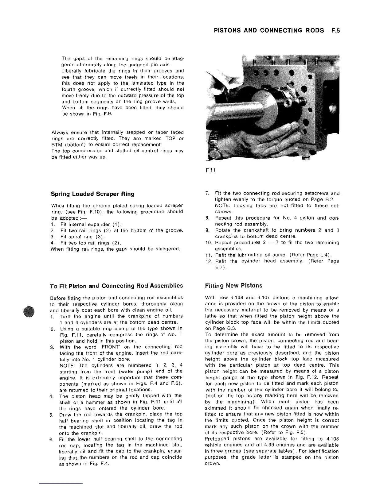
2.
Using a
suitable
ring
clamp
of
the type
shown
in
Fig. F.11,
carefully
compress
the
rings
of
No. 1
piston and
hold
in this position.
3.
With the
word
'FRONT' on the
connecting
rod
facing
the
front
ot
the engine, insert the rod care-
fully into
No.1
cylinder
bore.
NOTE: The
cylinders
are numbered
1,
2,
3,
4
starting from the
front
(water
pump)
end
of
the
engine. It is extremely
important
that
these com-
ponents
(marked
as
shown
in Figs. F.4 and F.5),
are
returned
to
their
original
locations.
4.
The piston head may be
gently
tapped
with
the
shaft
of
a
hammer
as shown in Fig.
F.11
until
all
the rings have entered
the
cylinder
bore.
5.
Draw the rod
towards
the
crankpin,
place the top
half bearing shell in
position
locating
the tag in
the
machined
slot and
liberally
oil,
draw
the rod
onto
the
crankpin.
6.
Fit
the
lower
half
bearing shell
to
the
connecting
rod cap,
locating
the tag in
the
machined
slot,
liberally
oil
and
fit the
cap
to
the
crankpin,
ensur-
ing that the numbers on
the
rod and
cap
coincide
as shown in Fig. F.4.
PISTONS AND CONNECTING
RODS-F.S
F11
7.
Fit the
two
connecting
rod
securing
setscrews
and
tighten
evenly
to
the
torque
quoted
on Page B.2.
NOTE:
Locking
tabs are
not
fitted
to
these
set-
screws.
8.
Repeat
this
procedure
for
No. 4
piston
and
con-
necting
rod assembly.
9.
Rotate
the
crankshaft
to
bring
numbers
2
and
3
crankpins
to
bottom
dead centre.
10. Repeat
procedures
2 - 7
to
fit the
two
remaining
assemblies.
11. Refit the
lubricating
oil sump.
(Refer
Page
L.4).
12. Refit the
cylinder
head assembly.
(Refer
Page
E.7).
Fitting
New
Pistons
With
new 4.108
and
4.107
pistons
a
machining
allow-
ance
is
provided
on the
crown
of
the
piston
to
enable
the
necessary
material
to
be removed by means
of
a
lathe
so
that
when
fitted the
piston
height
above the
cylinder
block
top
face
will
be
within
the
limits
quoted
on Page B.3.
To
determine
the
exact
amount
to be removed from
the
piston
crown, the piston,
connecting
rod and bear-
ing
assembly
will
have
to
be
fitted
to
its respective
cylinder
bore
as
previously
described,
and
the
piston
height
above
the
cylinder
block
top
face measured
with
the
particular
piston
at
top
dead centre. This
piston
height
can be measured by means of a
piston
height
gauge
of
the
type
shown
in Fig. F.12. Repeat
for
each
new
piston
to
be
fitted
and
mark
each piston
with
the
number
of
the
cylinder
bore
it
will
belong
to,
(not
on
the
top
as any
marking
here
will
be removed
by the
machining).
When
each
piston
has been
skimmed
it
should
be
checked
again
when finally re-
fitted
to
ensure
that
any new
piston
fitted is
now
within
the
limits
quoted.
Once
the
piston
height
is
correct
mark
any
such
piston
on the
crown
with
the
number
of
its
respective
bore.
(Refer
to
Fig. F.5).
Pretopped
pistons
are
available
for
fitting to 4.108
vehicle
engines
and
all
4.99
engines
and are available
in
three
grades
(see
separate
tables).
For
identification
purposes,
the
grade
letter
is
stamped
on the
piston
crown.