the valve in
the
outlet
port
fitted in the reverse
position.
3.
Press the valves home with a suitable
piece
of
tubing.
approximately
9/16
in (14,29
mm)
inside
diameter
and
{f
in (19,05
mm)
outside diameter.
4.
Stake the
casting
in six places
(between
the
original
stakings)
round each valve, with a suitable
punch.
NOTE: Valves fitted
to
earlier
lift
pumps were
held in
position
with a retaining plate and
two
screws. On
no
account
should attempts be made
to
stake the valves of this
earlier
type pump.
5.
Place the
rocker
arm retaining pin in the appro-
priate hole in the
lower
casting and push
through
until it
protrudes
slightly inside.
6. Fit one
packing
washer and the
link
into
the
casting
moving the
pin
in slightly
to
retain them.
7. Fit the
rocker
arm and return
spring
and retain by
moving the
pin
in further, ensuring that the
spring
seats
correctly.
8. Fit the
remaining
packing washer, then push
the
rocker
arm retaining pin through the link, washer
and
casting
until
the ends
protrude
equally beyond
the outside
of
the
casting.
9.
Retain by
securing
with the
two
clips.
10. Insert the
new
rubber
sealing washer
followed
by
the steel seating washer and
diaphragm
return
spring.
11. Place the
diaphragm
assembly
over
the
spring
with the pull rod downwards,
locating
the
top
of
the
spring
in
the
diaphragm
protector
washer.
12.
Now
position
the
pull rod
so
that the flat
notched
blade
has one
of
its
thin
edges
facing
the
rocker
arm. Press
downwards
on the
diaphragm
assembly
and
twist
it
through
90" in
either
direction,
this
action
will
engage and retain the pull rod in
the
fork
of
the link.
13. Operate the
rocker
arm
against
the
diaphragm
spring
pressure until the
diaphragm
is level
with
the
body
flange.
14. Place the
cover
assembly in
position
and line
up
the
file
marks
made on the flanges
prior
to
dismantling.
15. Still
holding
the
diaphragm
level
with
the
body
flanges, fit
the
five flange
securing
screws,
tighten
evenly and securely.
To Refit the Fuel
lift
Pump
1.
Fit
the
distance
piece using a
joint
on
either
side.
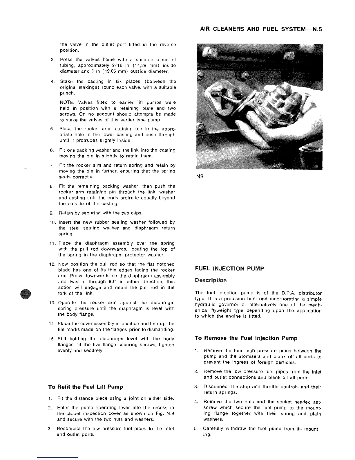
2.
Enter
the pump
operating
lever
into
the
recess in
the
tappet
inspection
cover
as shown on Fig. N.9
and
secure
with
the
two
nuts and washers.
3.
Reconnect
the
low pressure fuel pipes to the
inlet
and
outlet
ports.
AIR CLEANERS AND FUEL
SYSTEM-N.S
N9
FUEL INJECTION PUMP
Description
The fuel
injection
pump
is
of
the D.P.A.
distributor
type.
It
is a
precision
built
unit
incorporating
a
simple
hydraulic
governor
or
alternatively
one
of
the mech-
anical
flyweight
type
depending
upon
the
application
to
which
the
engine
is fitted.
To
Remove
the
Fuel
Injection
Pump
1. Remove
the
four
high
pressure
pipes
between
the
pump
and
the
atomisers
and
blank
off all
ports
to
prevent
the
ingress
of
foreign
particles.
2.
Remove the
low
pressure
fuel
pipes
from
the
inlet
and
outlet
connections
and
blank
off all ports.
3.
Disconnect
the
stop
and
throttle
controls
and
their
return
springs.
4.
Remove the
two
nuts and the
socket
headed set-
screw
which
secure
the fuel
pump
to
the mount-
ing
flange
together
with
their
spring
and plain
washers.
5.
Carefully
withdraw
the fuel
pump
from
its
mount-
ing.