AIR CLEANERS AND FUEL
SYSTEM-N.4
Pressure Checking
of
Fuel Lift Pump
in
Position
Fit a 0-10
Ibflin
2
(0-0,7
kgflcm2)
or
0-70
kN/m
2
pressure
gauge to
the
outlet
of the pump. Ensure that
there
are
no leaks at the
connections
between pump and gauge.
Crank
the engine
for
10 seconds and note the maximum
reading on the gauge. If the pressure recorded is less
than
75%
of the
minimum
production
static
pressure
shown below,
then
rectify the pump. Also observe the
rate at
which
the pressure
drops
to
half
the maximum
figure obtained
when
cranking
has ceased. If less than
30 seconds, rectFfy the pump.
4
bolt
type
2
bolt
type
Minimum
Production
Static Pressure
Ibflin
2
kgflcm2
kN/m
2
6 0,42
41
6 0,42
41
To Remove the Lift Pump
Minimum
Test Pressure
(75%
of Minimum
Production
Pressure)
Ibflin
2
kgflcm2
kN/m
2
4.5
0,31
31
4.5 0,31
31
1.
Disconnect
the pipes from
the
inlet
and
outlet
ports. Seal the
ends
of
the
pipes
to
prevent the
entry
of
foreign
matter.
2.
Remove the
two
nuts and washers
holding
the
pump
to
the
tappet
inspection cover.
Withdraw
the
pump,
distance
piece
and joints.
To Dismantle the Lift Pump
1. Before dismantling, make a file
mark
across
the
flanges
for
location
purposes when the
pump
is
being
re-assembled.
2.
Remove the five
cover
screws
and
separate the
two
main castings, then remove
the
diaphragm
assembly
from
the
lower
half by
turning
the dia-
phragm
through
90'
in
either
direction.
NOTE: The
diaghragm
and pull rod assembly is a
permanent
assembly and no
attempt
should be
made
to
separate
the
parts.
3.
Remove the retaining
clip
from one
side
of the
pump
body
and push
out
the
rocker
arm retaining
pin.
Withdraw
the
rocker
arm, etc., from the body.
4.
Prise
out
the valves with a
screwdriver
or
other
suitable
tool.
Inspection
I.
Check
the
diaphragm
assembly
and
renew if the
material is
split
or
cracked,
or
if
serious wear is
apparent
in the
link
engagement
slot.
2. The
diaphragm
spring
should
be
replaced
if
faulty
or
corroded.
A
new
spring
should
have the same
colour
identification
(Refer
to
Page
B.11).
3.
Replace the valves unless they
appear
to
be in per-
fect
condition.
4.
Examine the
rocker
arm,
operating
lever,
rocker
arm retaining pin
and
rocker
arm
return
spring
for
wear. Replace any
parts
where
necessary.
5.
Replace all joints,
seals
and
washers
as
routine
procedure.
6. Examine upper and
lower
castings
for
wear
or
distortion.
Slight
distortion
of
flanges
can
be
remedied by
grinding
the
flange
face
to restore
flatness.
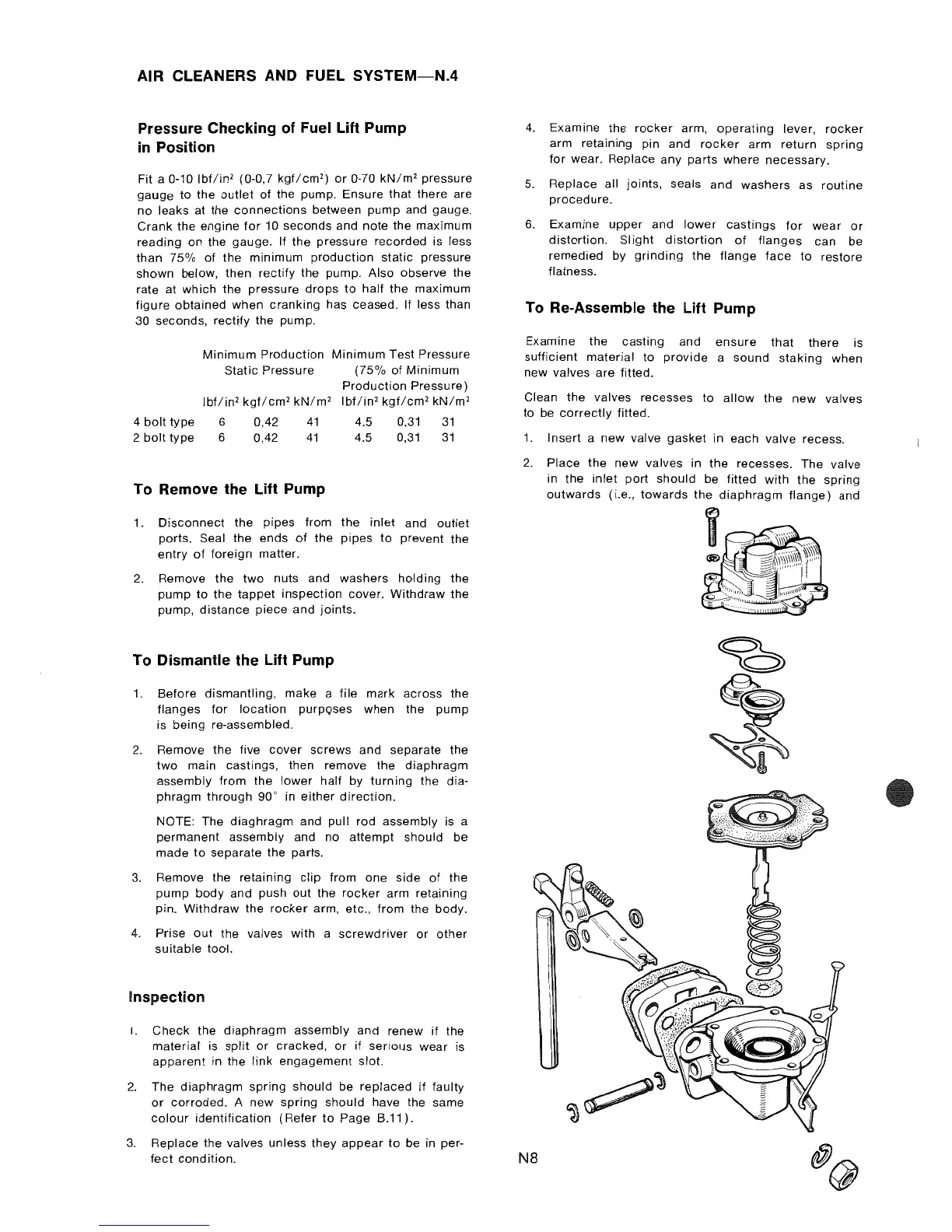
To Re-Assemble the Lift Pump
Examine the casting and
ensure
that
there is
sufficient material to
provide
a sound
staking
when
new valves
are
fitted.
Clean the valves recesses to
allow
the
new
valves
to be
correctly
fitted.
1.
Insert a
new
valve
gasket
in each valve recess.
2.
Place
the
new
valves in
the
recesses. The valve
in the
inlet
port
should
be fitted
with
the
spring
outwards
(i.e.,
towards
the
diaphragm
flange)
and
N8