PISTONS AND CONNECTING
RODS-F.2
!nspection
1. Examine
the
pistons
for
scoring
and any
signs
of
groove damage.
2.
Check the
clearance
of
the
piston rings in
their
respective
grooves
by placing the ring outer face
into the
groove
and a suitable sized feeler between
the ring and
groove
face.
NOTE: All
ring
gaps, ring groove
clearances
etc.,
are
given in the Technical Data
Section
on Page
B.4.
3.
Check
the
fitted gaps
of
the piston rings, bearing
in mind that in worn
cylinder
bores these gaps
should be
checked
at
the
bottom
of
the bore.
4.
Check the fit
of
the
gudgeon
pin
in the small end
bush, if
excessive, replace the small end bush.
5.
To renew the small end bush, remove the old one
by means
of
a suitable press and
'dolly'.
Press in
the new bush, ensuring
that
the oil holes
coincide
when fitted. Ream out the new bush to suit the
gudgeon pin, then
check
the rod
for
parallelism
and twist.
(Refer
Page
B.5).
6.
Examine the big end bearing shells
for
any
signs
of
wear
or
pitting.
To Refit the Pistons
to
the Connecting Rods
If the
original
pistons
are to be refitted they must be
re-assembled to the same
connecting
rods, i.e. No. 1
piston
to
No.1
connecting
rod assembly. Refer
to
Figs.
F.4 and F.5
for
location
of
piston and rod
numbering.
Any new
components
fitted
should
be numbered
the
same as those
which
they replace.
Note:
Where
controlled
expansion pistons are fitted,
these
have a 0.020 in (0,51
mm)
off-set
gudgeon
pin
towards
the camshaft side
of
the engine and when
replacing
these pistons, they
must
be fitted
the
correct
way round, i.e.,
the
word
"FRONT"
or
arrow
on
the
piston crown
to
the
front
of
the
engine. If
these
marks
have been removed by
machining
the crown,
then
the
small round recess in the
gudgeon
pin
bore
'A'
Fig.
F.6, must face
the
front
of
the engine.
Where
controlled
expansion pistons
with
off-set
pins
are fitted, the latest phosphated
crankshaft
pulley
setscrew
must be used.
1.
Warm the piston in a
suitable
clean
liquid
to
a
temperature
of
100 -
120'F
(40 -
50"C)
which
will
enable
the
gudgeon
pin
to
be easily pushed
into the
piston
bore
when the
piston
and
rod have
been
correctly
aligned
F5
•
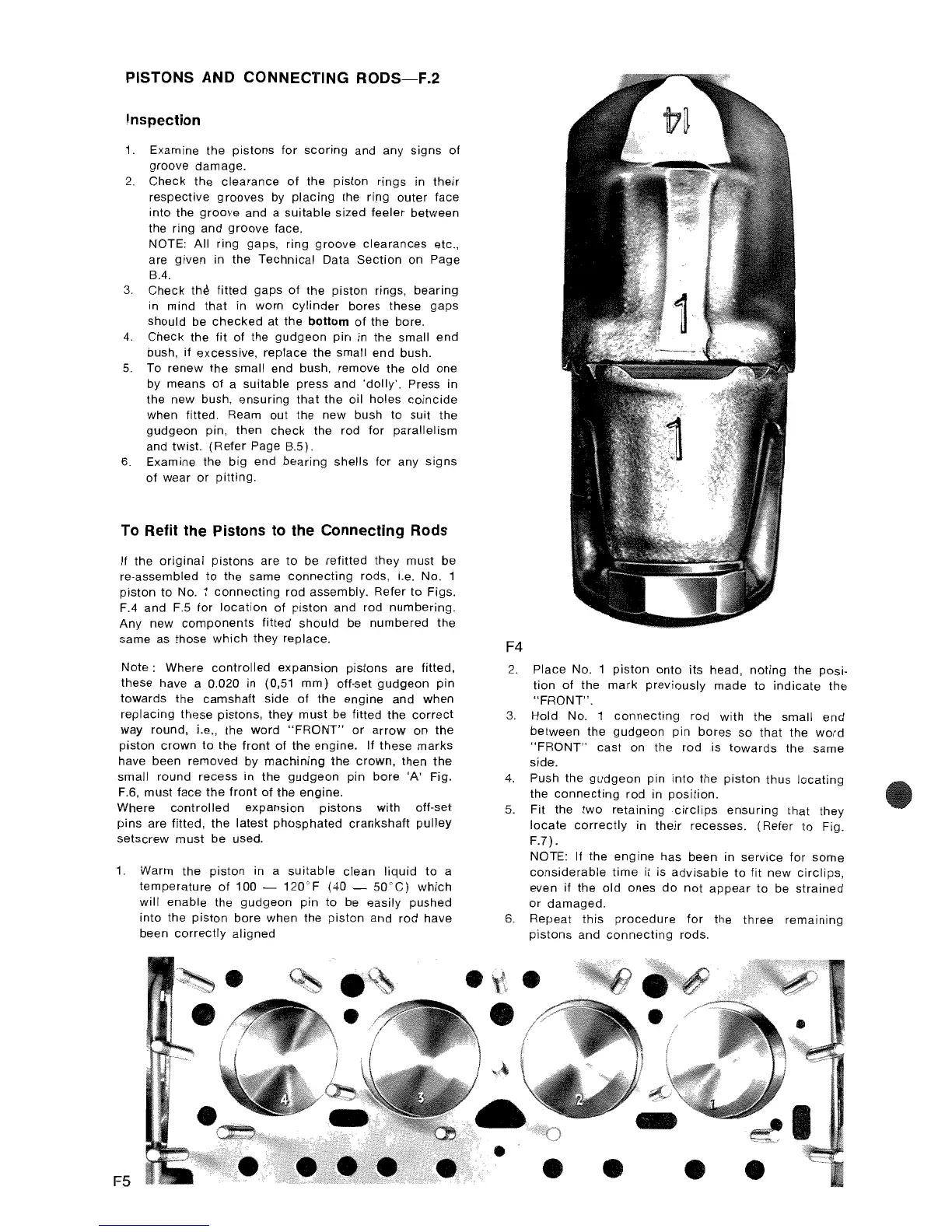
F4
2.
Place No. 1
piston
onto
its
head,
noting
the posi-
tion
of
the
mark
previously
made
to
indicate
the
"FRONT".
3.
Hold No. 1
connecting
rod
with
the small end
between the
gudgeon
pin bores so
that
the
word
"FRONT"
cast
on the rod is
towards
the same
side.
4.
Push the
gudgeon
pin
into
the
piston
thus
locating
the
connecting
rod in
position.
5. Fit the
two
retaining
circlips
ensuring
that
they
locate
correctly
in
their
recesses. (Refer
to
Fig.
F.7).
NOTE: If the
engine
has been in
service
for
some
considerable
time
it is
advisable
to fit new
circlips,
even if the old
ones
do
not
appear
to
be
strained
or
damaged.
6. Repeat this
procedure
for
the
three
remaining
pistons
and
connecting
rods.
•
•
•
• •