CYLINDER
HEAD-E.6
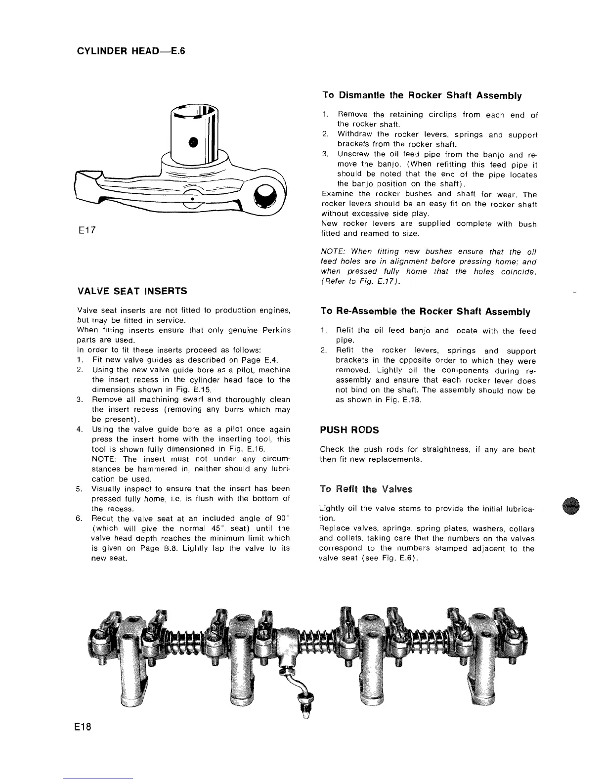
E17
~
I
•
VALVE SEAT INSERTS
Valve seat inserts
are
not
fitted to
production
engines,
but
may be fitted in service.
When fitting inserts ensure
that
only
genuine
Perkins
parts
are used.
In
order
to fit these inserts
proceed
as follows:
1.
Fit
new valve
guides
as
described
on Page E.4.
2.
Using the
new
valve
guide
bore
as a pilot,
machine
the insert recess in the
cylinder
head face to the
dimensions
shown
in Fig. E.15.
3.
Remove all
machining
swarf
and
thoroughly
clean
the insert recess
(removing
any burrs
which
may
be
present).
4.
Using the valve
guide
bore
as a
pilot
once
again
press the insert home
with
the
inserting
tool, this
tool is shown fully
dimensioned
in Fig. E.16.
NOTE: The insert must
not
under
any
circum-
stances be hammered in,
neither
should
any lubri-
cation
be used.
5. Visually
inspect
to ensure
that
the
insert has been
pressed fully home, i.e. is flush
with
the
bottom
of
the recess.
6. Recut
the
valve seat at an
included
angle of
90'
(which
will
give
the
normal
45'
seat) until
the
valve head
depth
reaches the
minimum
limit
which
is given on Page B.8.
Lightly
lap
the valve to its
new
seat.
E18
To
Dismantle the Rocker Shaft Assembly
1.
Remove the retaining
circlips
from
each
end
of
the
rocker
shaft.
2.
Withdraw
the
rocker
levers,
springs
and
support
brackets
from the
rocker
shaft.
3.
Unscrew the oil feed
pipe
from
the
banjo
and
re-
move the banjo.
(When
refitting
this
feed
pipe
it
should be noted
that
the
end
of
the
pipe
locates
the
banjo
position
on the
shaft).
Examine the
rocker
bushes and
shaft
for
wear. The
rocker
levers
should
be an easy fit on the
rocker
shaft
without
excessive
side
play.
New
rocker
levers are
supplied
complete
with
bush
fitted and reamed
to
size.
NOTE: When
fitting
new
bushes
ensure
that the
oil
feed holes are
in
alignment
before
pressing
home;
and
when
pressed
fully
home
that the
holes
coincide.
(Refer to Fig.
£,17).
To Re-Assemble the Rocker Shaft Assembly
1.
Refit the
oil
feed
banjo
and
locate
with
the feed
pipe.
2.
Refit the
rocker
levers,
springs
and
support
brackets
in the
opposite
order
to
which
they
were
removed.
Lightly
oil
the
components
during
re-
assembly
and ensure
that
each
rocker
lever
does
not
bind
on the shaft. The
assembly
should
now
be
as shown in Fig. E.18.
PUSH RODS
Check
the push
rods
for
straightness, if any are
bent
then fit new replacements.
To Refit
the
Valves
Lightly
oil
the valve stems
to
provide
the
initial
lubrica-
tion.
Replace valves,
springs,
spring
plates, washers,
collars
and
collets,
taking
care
that the
numbers
on the valves
correspond
to the
numbers
stamped
adjacent
to
the
valve seat
(see
Fig.
E.6).