SECTION P
Flywheel and Flywheel Housing
To Remove
the
Flywheel
1.
Remove the gearbox,
clutch
assembly and any
linkage
as
detailed
in the service literature applic-
able
to the
particular
vehicle
or
application.
2.
Knock
back
the
locking
tabs from the flywheel
securing
setscrews.
3.
Remove the securing setscrews and
carefully
re-
move
the
flywheel from the
crankshaft
flange.
To Renew the Flywheel Ring Gear
1. The flywheel ring
gear
is a
shrunk
fit on the fly-
wheel, its removal is
carried
out by
partially
cut-
ting
through
the
gear
and chisel
cutting
it from
the
flywheel. An alternative method is
to
apply
localised
heat
to the ring gear to expand it
sufficiently
to enable
it
to
be tapped evenly from
the flywheel.
2.
The
locating
faces
of
the
flywheel
should
be
thoroughly
cleaned
to
ensure a
positive
location
when
the
new
ring
gear
is fitted.
3.
Clean, then heat the
new
ring
gear
to a tempera-
ture
not
exceeding
480°F
(250
Q
C).
4.
Fit the ring
gear
over the flywheel
with
the lead on
the
teeth facing uppermost, i.e.,
facing
away from
the
engine
when the flywheel is fitted. Rotate the
gear
quickly
on its
location
immediately
it is fitted
to ensure it is laying flat, then
allow
to
cool.
To Refit the
1"1",.11'
..
""
..
1
It is most essential to ensure that the
crankshaft
flange
face and
periphery
are
perfectly
clean and free from
burrs,
similarly
the mating face
of
the flywheel
itself
before refitting
of
the flywheel is attempted. Failure
to
ensure
this
may make
it
impossible
to
fit
the flywheel
satisfactory
within
the
various
limits
quoted
hereafter.
It will be noted that there is a sixth
(untapped)
hole in
the
crankshaft
flange
which
will be
at
B.D.C.
when
Nos. 1
and
4 pistons are at T.O.C.
The flywheel can only be fitted in one
position
due to
the
irregular
spacing
01
the setscrew holes.
1.
It
is
advisable
to
screw
a
short
stud
into
the crank-
shaft flange
just
finger
tight, so that when the fly-
wheel is offered up this stud can take the
weight
of
the flywheel
whilst
the
securing
setscrews
are
fitted, this stud can
then
be removed and re-
placed
by the fifth setscrew.
2.
Tighten
the
securing
setscrews
to the
torque
given
on
Page B.2
but
do
not
lock
with
the
tab
washers
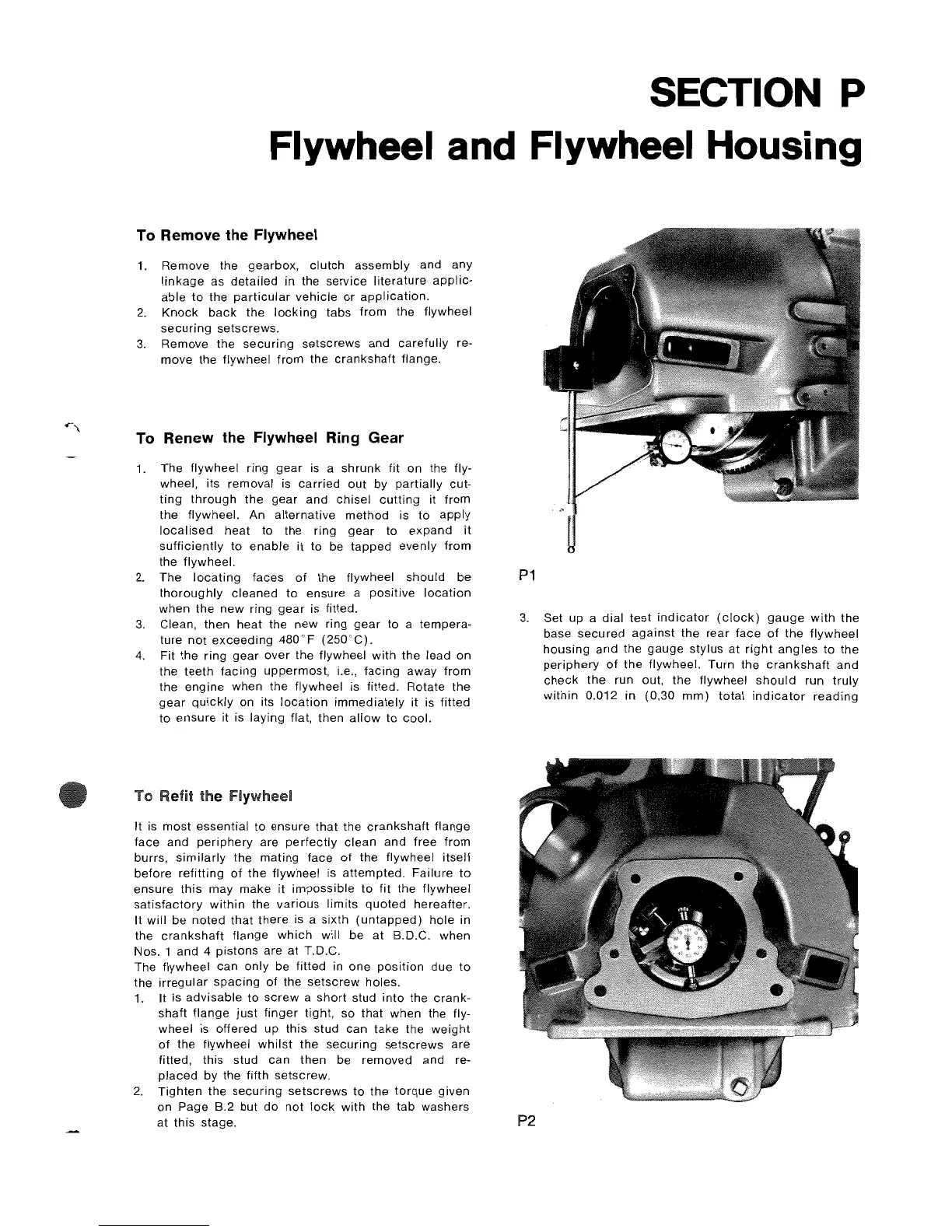
P1
3.
Set
up
a
dial
test
indicator
(clock)
gauge
with
the
base
secured
against
the
rear
face
of
the
flywheel
housing
and the
gauge
stylus
at
right
angles
to
the
periphery
of
the
flywheel. Turn the
crankshaft
and
check
the run out,
the
flywheel
should
run
truly
within
0.012 in (0,30
mm)
total
indicator
reading
at
this
stage.
P2