Fuel Pipes
(High
Pressure)
When replacing the fuel pipes it should
be
noted that
no two pipes are the same, each
is
formed to suit
an
individual atomiser position. This is important when
ordering a replacement pipe, as each one has a
different part number.
High pressure fuel pipes are now supplied with formed
ends instead of olives. The earlier pipes supplied with
olives were fitted as shown in Fig. N.21. Originally the
olives were fitted in the reverse position, but both
positions are satisfactory if undamaged.
N21
The pipes should be clean,
(wash
in clean fuel oil and
blow
through
the
fine
bore
with
compressed air
if
there
is
any
doubt),
the
olives
at
each end should
not
be split
or
unduly
compressed,
otherwise
leakage
will
result and a
new
pipe
will
be needed.
Ensure when fitting, that the pipe fits squarely at both
ends and that the union nuts are tightened firmly but
not over-tightened.
The correct tightening torque
for
high pressure fuel
pipe nuts is
15
Ibf ft
(2,1
kgf m)
or
20
Nm.
When changing an atomiser always remove the pipe
completely.
The air must
be
vented from the fuel system whenever
any part
of
the system between the fuel tank and in-
jection pump has been disconnected
for
any reason,
or
when the system has been emptied of fuel.
No
attempt
must
be made
to
start
the
engine
until
the
injection
pump
has been filled and primed as serious
damage can be caused
to
the
pump
due
to
lack
of
lubrication.
The method of priming detailed below, ensures that
only fuel which has passed through the paper filter
element can reach the interior of the pump.
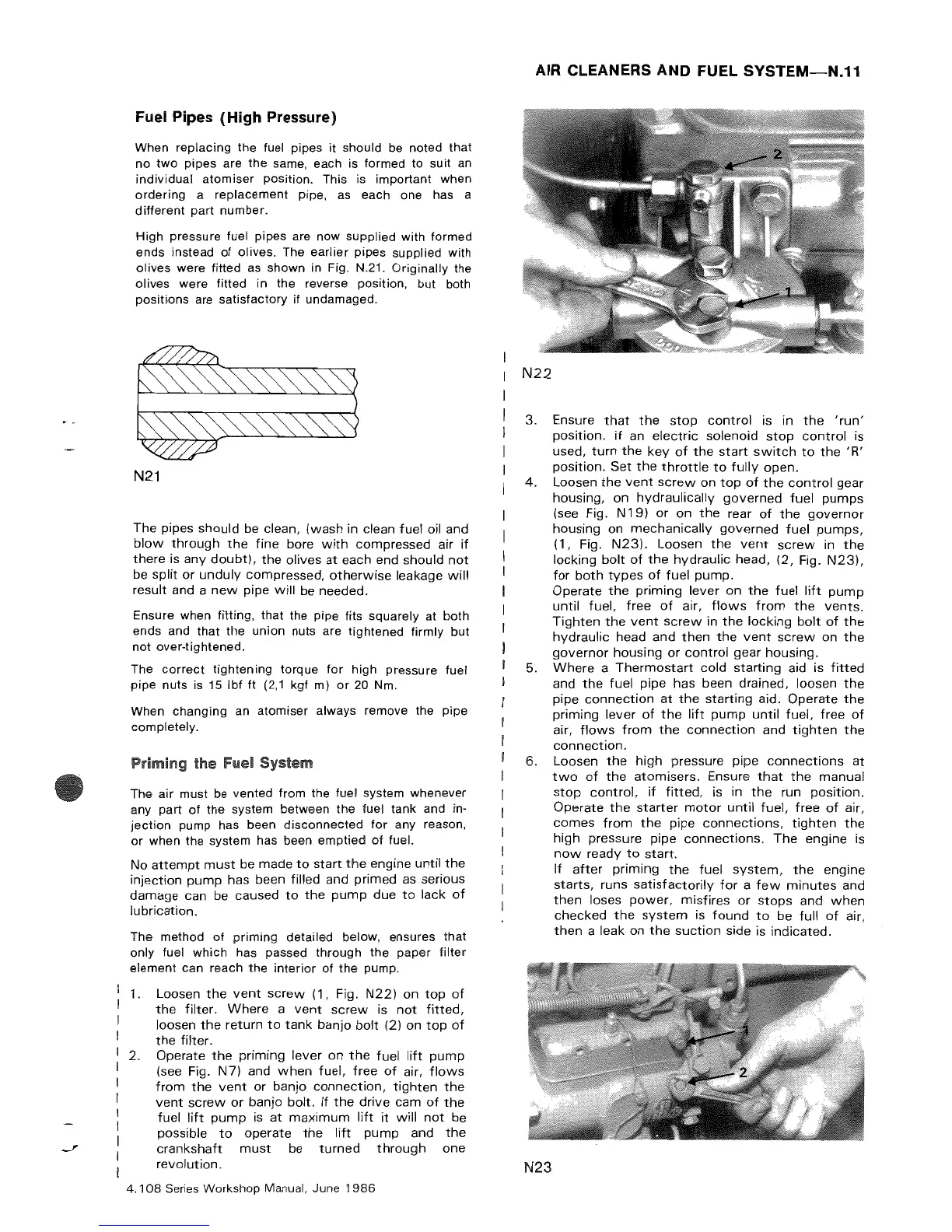
1. Loosen
the
vent
screw
(1, Fig.
N22)
on
top
of
the
filter.
Where
a
vent
screw
is
not
fitted,
loosen
the
return
to
tank
banjo
bolt
(2) on
top
of
the
filter.
2. Operate
the
priming lever
on
the
fuel
lift
pump
(see Fig.
N7)
and
when
fuel,
free
of
air,
flows
from
the
vent
or
banjo
connection,
tighten
the
vent
screw
or
banjo bolt. If
the
drive
cam
of
the
fuel
lift
pump
is
at
maximum
lift
it
will
not
be
possible
to
operate
the
lift
pump
and
the
-'
crankshaft
must
be
turned
through
one
revolution.
4.108
Series
Workshop Manual, June
1986
AIR
CLEANERS AND FUEL
SYSTEM-N.11
N22
3. Ensure
that
the
stop
control
is in
the
'run'
position.
if
an
electric
solenoid
stop
control
is
used,
turn
the
key
of
the
start
switch
to
the
'R'
position.
Set
the
throttle
to
fully
open.
4.
Loosen
the
vent
screw
on
top
of
the
control
gear
housing, on
hydraulically
governed
fuel
pumps
(see Fig. N
19)
or
on
the
rear
of
the
governor
housing on
mechanically
governed
fuel
pumps,
(1, Fig.
N23).
Loosen
the
vent
screw
in
the
locking
bolt
of
the
hydraulic
head,
(2,
Fig.
N23),
for
both
types
of
fuel
pump.
Operate
the
priming
lever on
the
fuel
lift
pump
until
fuel,
free
of
air,
flows
from
the
vents.
Tighten
the
vent
screw
in
the
locking
bolt
of
the
hydraulic
head and
then
the
vent
screw
on
the
governor
housing
or
control
gear
housing.
5.
Where
a
Thermostart
cold
starting
aid is
fitted
and
the
fuel pipe has been drained, loosen
the
pipe
connection
at
the
starting
aid.
Operate
the
priming
lever
of
the
lift
pump
until
fuel,
free
of
air,
flows
from
the
connection
and
tighten
the
connection.
6. Loosen
the
pressure pipe
connections
at
N23
two
of
the
atomisers.
Ensure
that
the
manual
stop
control,
if
fitted,
is in
the
run
position.
Operate
the
starter
motor
until
fuel,
free
of
air,
comes
from
the
pipe
connections,
tighten
the
high
pressure pipe
connections.
The
engine is
now
ready
to
start.
If
after
priming
the
fuel
system,
the
engine
starts,
runs
satisfactorily
for
a
few
minutes
and
then
loses
power,
misfires
or
stops
and
when
checked
the
system
is
found
to
be
full
of
air,
then
a leak
on
the
suction
side is indicated.