NOTE: Valve
springs
incorporate a
damper
coil
and
care
should
be
taken
to ensure that this
damper
coil
is
to
the
bottom
of
the
spring
i.e., nearest the
cylinder
head
when
fitted.
Inner valve
springs
are
not
required for engines rated
at
3,000
rev/min
and
below.
4.108
engines
and 4.99 vehicle engines are fitted with
rubber
sealing rings on
inlet
valves only.
All
latest 4.107 and 4.99
agricultural
and industrial
engines
incoroporate
oil
deflectors
on both
inlet
and
exhaust valves.
In the case
of
earlier
4.107 and 4.99
agricultural
and
industrial
engines
which
incorporate
rubber
sealing
rings
on
the
inlet
valves only, oil
deflectors
should be
fitted
to
both inlet and exhaust valves
after
the valve
assembly has been
dismantled.
With this arrangement,
a
different
valve
spring
seating washer is required
for
exhaust
vales.
Where a
groove
is
cut
on the
inlet
valve stem, a
rubber
sealing
washer
should
be fitted in
addition
to
the de-
flector
to
stop
the
later
from
becoming
canted
on the
stem.
Oil
deflectors
should not be fitted to 4.99
vehicles
and
some 4.108 engines.
CYLINDER HEAD GASKET
Always use a
new
cylinder
head gasket. Ensure that
the
correct
type is used.
4.108 Engines
With
this
engine, the
gasket
is made
of
a
black
com-
posite material and is known
as
the
Klinger
type. It
MUST be fitted DRY and on
no
account
should
joint-
ing
compound
be used.
It is very
important
that the gasket is
placed
correctly,
otherwise
the steel
beading
may be
nipped
between
the
cylinder
head face and the
top
of the liner.
4.107
and
4.99
These engines use a
copper
and asbestos
or
a copper,
steel and asbestos gasket. These gaskets
should
be
fitted
with
a
light
coating
of
Perkins
(Hylomar)
jointing
compound
on both sides.
To
Rem
Cylinder
Head
1. Place the
cylinder
head
gasket
carefully
in posi-
tion
on the
cylinder
block
face
(the
gasket
is
marked
"TOP
FRONT" to
indicate
how
it
should
be
fitted).
(Refer
to Fig. E.22).
2.
Lower
the
cylinder
head
into
position
on
top
of
the
gasket
ensuring that it lays
perfectly
level.
3.
Lightly
lubricate
both
cylinder
head
studs
and nuts
with
engine
oil, then
tighten
the nuts
progressively
in three stages in the
sequence
shown
in Fig. E.23
to
the
torque
given on page B.2.
This
final
torque
tightening
stage should be repeated to ensure
that
no
loss
of
tension has taken place on any studs
earlier
in
the
sequence.
With
current
engines,
washers
are fitted
under
the
cylinder
head nuts
which
necessitates
longer
cylinder
head studs. The
cylinder
head
tightening
torque
re-
mains
unaltered.
CYLINDER
HEAD-E.1
1
II
F"t---2
---_
3
6
7 8
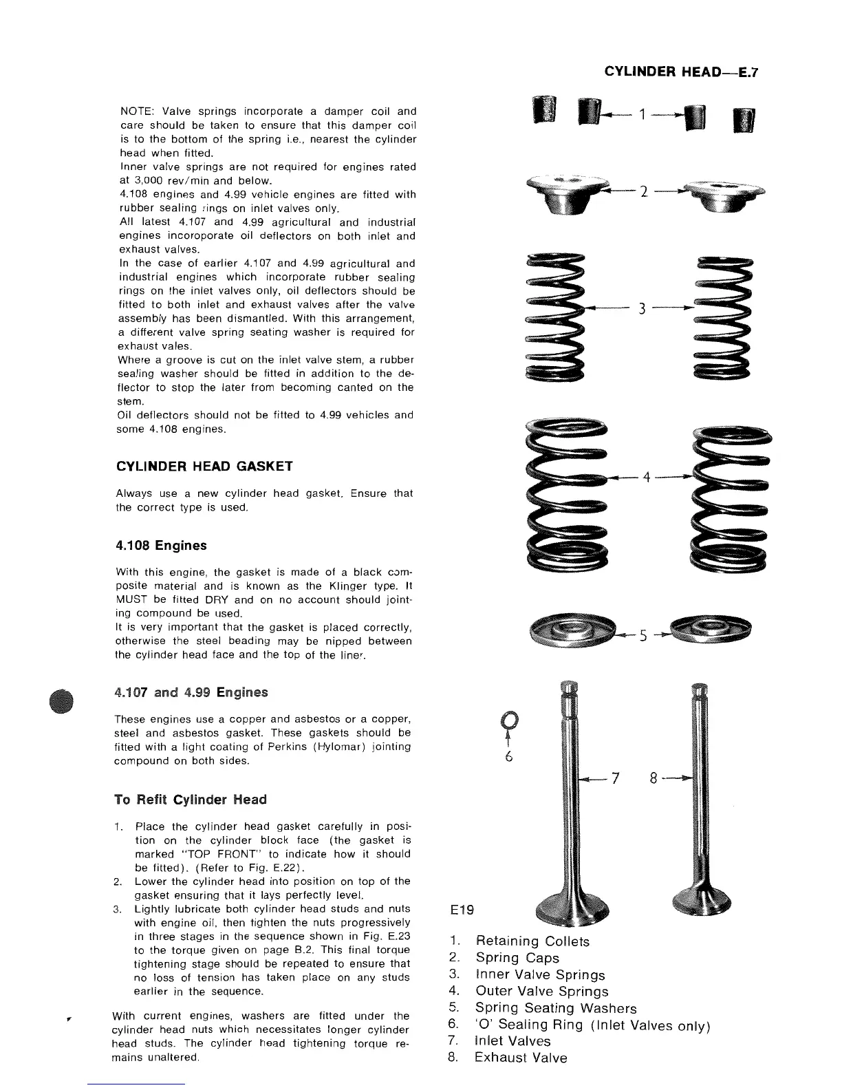
E19
1.
Retaining
Collets
2.
Spring
Caps
3.
Inner
Valve
Springs
4.
Outer
Valve
Springs
5.
Spring
Seating
Washers
6.
'0'
Sealing
Ring
(Inlet
Valves
only)
7.
Inlet
Valves
8.
Exhaust
Valve