Page 3
FOREWORD
This
workshop
manual has been
compiled
for
use in
conjunction
with
normal
workshop
practice.
Mention
of
certain
accepted
practices
therefore, has been purposely
omitted
in
order
to
avoid
repetition.
Reference to renewing
joints
and cleaning off
joint
faces has to a
great
extent
been
omitted
from
the text, it being understood
that
this will be
carried
out
where
applicable.
Similarly,
it
is
understood
that
in reassembly and inspection, all parts are
to
be
thoroughly
cleaned
and where present,
burrs
and scale are to be removed.
It
follows
that any open ports
of
high
precision components, e.g., fuel
injection
equipment,
ex-
posed
by
dismantling, will be
blanked
off until reassembled, to prevent the
ingress
of
foreign
matter.
: When setscrews
or
studs are fitted into holes which are
tapped
through
into
the
inside
of
: the engine, a
suitable
sealant must be used on the threads.
Throughout
this manual, whenever the
"left"
or
"right"
hand side
of
the
engine
is
referred
to, it is
that
side
of
the
engine
as viewed from the flywheel end.
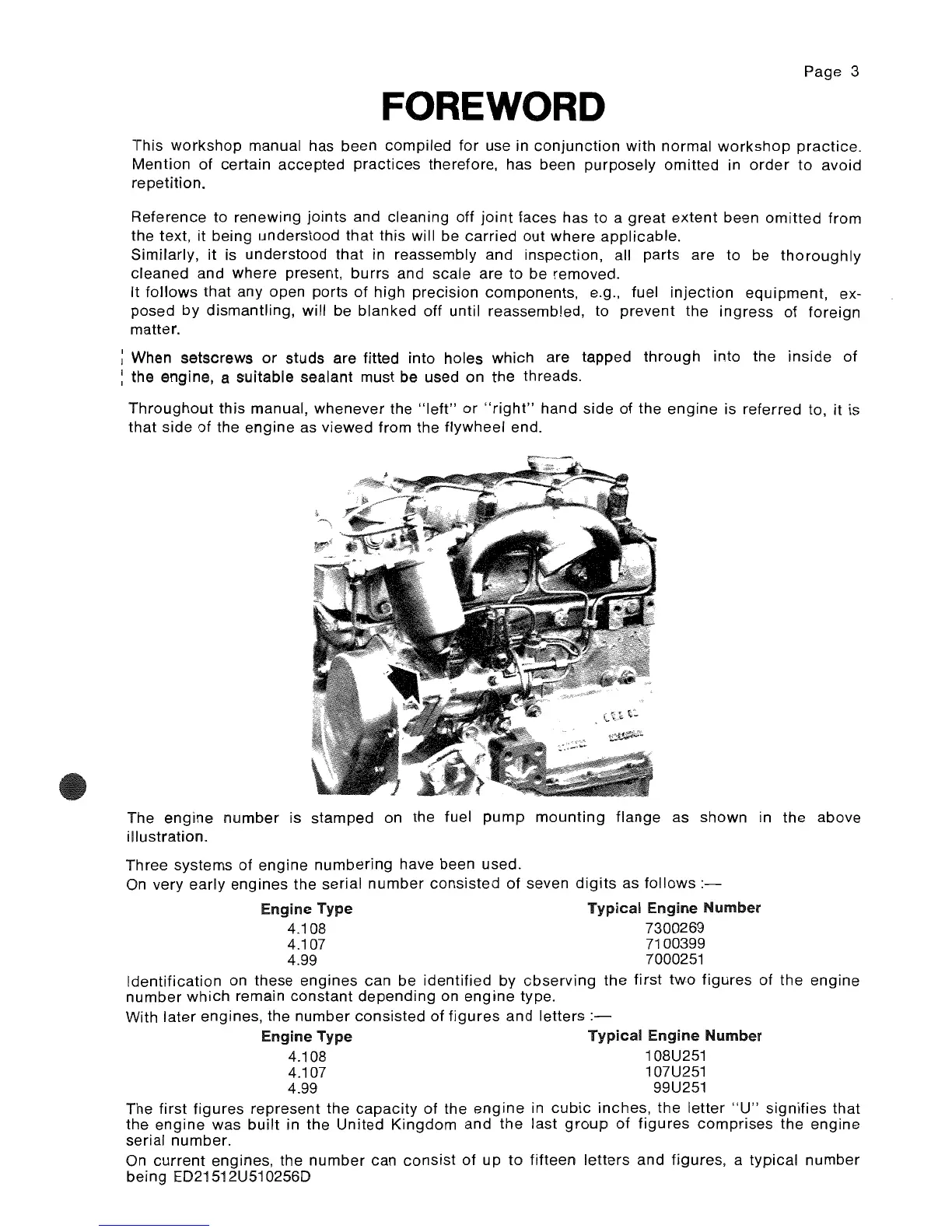
The
engine
number
is stamped on the fuel
pump
mounting
flange
as shown in
the
above
illustration.
Three systems
of
engine
numbering
have been used.
On
very early engines the serial
number
consisted
of
seven
digits
as
follows
:-
Engine Type
Typical
Engine
Number
4.108 7300269
4.107 7100399
4.99 7000251
Identification
on these
engines
can be
identified
by
cbserving
the
first
two
figures
of
the
engine
number
which
remain
constant
depending
on
engine
type.
With
later
engines, the
number
consisted
of
figures
and
letters
Engine Type
Typical
Engine
Number
4.108 108U251
4.107 107U251
4.99 99U251
The first
figures
represent the
capacity
of
the
engine
in
cubic
inches,
the
letter
"U"
signifies
that
the
engine
was
built
in the
United
Kingdom
and
the
last
group
of
figures
comprises
the engine
serial number.
On
current
engines, the
number
can
consist
of
up
to
fifteen
letters
and
figures, a typical
number
being ED21512U510256D