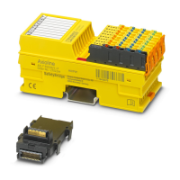
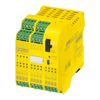
Hardware: PSR-TRISAFE-S safety module
103503_en_03 PHOENIX CONTACT 3-17
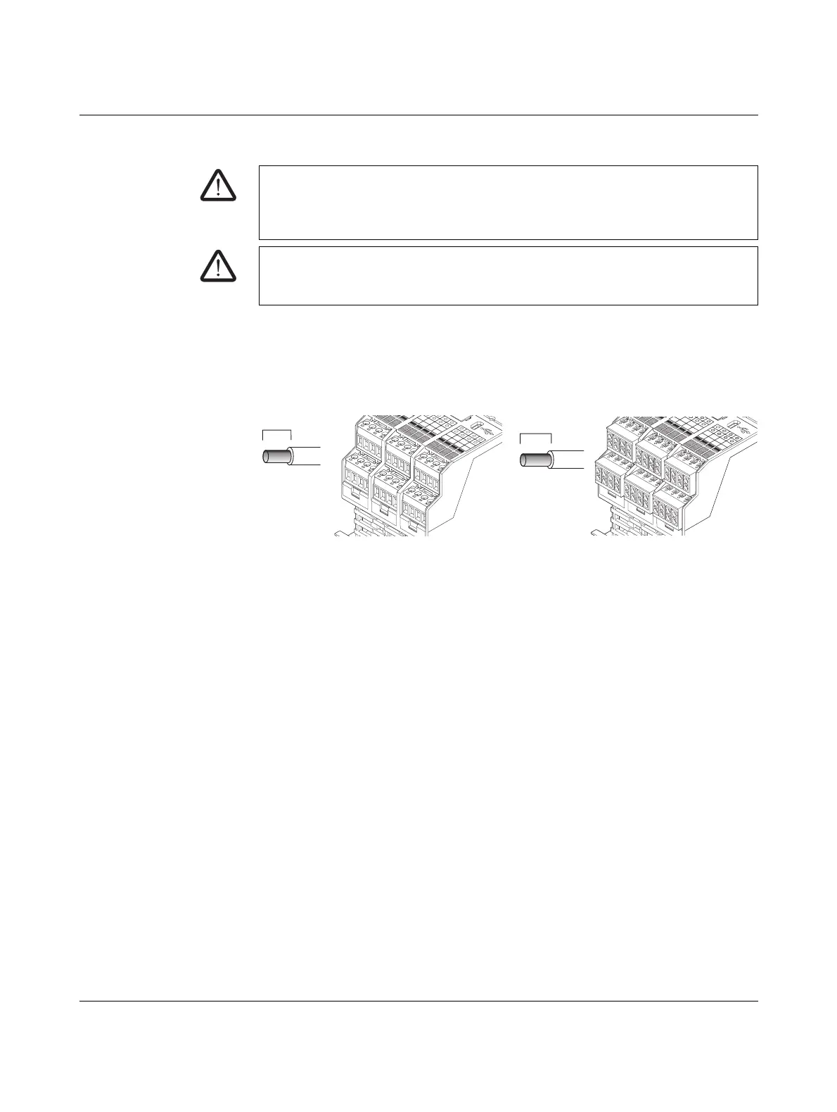
3.7.3 Connecting the signal lines
Cable lengths Many applications use large numbers of sensors or control devices. Depending on the size
of the machine or system, a considerable amount of cabling may be required to wire the
sensors. Make sure that the specified cable lengths are not exceeded, so as to ensure error-
free operation of the safety circuits and therefore a reliable safety demand.
For reliable and touch proof contacts, strip the cable ends as follows:
Figure 3-12 Connection to screw terminal blocks (left) and spring-cage terminal blocks
(right)
VORSICHT: Ensure signal redundancy.
Ensure signal redundancy when connecting the signal lines of two-channel control
devices and sensors to the inputs of the safety module. Please refer to "Signal inputs" on
page 3-7.
VORSICHT: Avoid cross circuits and short circuits.
Prevent cross circuits and short circuits by using a suitable cable installation. Implement
cross-circuit detection (see "Cross-circuit detection" on page 3-8).
7mm
I8
I4
I12
I9
I5
I13
I10
I6
I14
I11
I7
I15
I16
I17
I18
I19
C
Screw
terminal
8mm
I8
I12
I9
I5
I13
I10
I6
I14
I11
I7
I15
I16
I17
I18
I19
N
Spring-cage
terminal
blocks
 Loading...