103503_en_03 PHOENIX CONTACT A-1
A Appendix
A.1 List of figures
Section 1
Figure 1-1: Calling the online help in the SAFECONF configuration software ......1-8
Section 2
Figure 2-1: Typical structure of a safety system with PSR-TRISAFE-S ................2-1
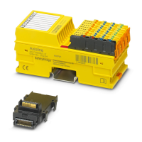
Figure 2-2: PSR TBUS DIN rail connector from Phoenix Contact ........................2-3
Figure 2-3: Implementing a startup inhibit, restart inhibit, and stop category 0
for safe output O0 ..............................................................................2-7
Figure 2-4: Implementing cross-circuit detection for an emergency stop
control device at inputs I0 and I1 of the safety module .......................2-8
Figure 2-5: Parameterizing cross-circuit detection for a module input ..................2-9
Figure 2-6: Simplified schematic view: Hardware diagnostics in the event of
an error at a safe functional block ....................................................2-10
Figure 2-7: Simplified schematic view: Wiring check .........................................2-11
Figure 2-8: Example of an online tool tip in the event of an error ........................2-12
Figure 2-9: Examples of tool tips in the connection editor in offline mode
(while editing the safety logic) ..........................................................2-12
Figure 2-10: Password protection for the PSR-TRISAFE-S and SAFECONF ......2-13
Section 3
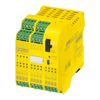
Figure 3-1: PSR-TRISAFE-S safety module with screw connection (left)
or with spring-cage terminal blocks (right), on 35 mm EN DIN rail .....3-1
Figure 3-2: Block diagram for the PSR-TRISAFE-S safety module ......................3-2
Figure 3-3: Diagram: Possible operating modes (status) for the
PSR-TRISAFE-S safety module ........................................................3-3
Figure 3-4: Operating and indication elements of the PSR-TRISAFE-S
safety module ....................................................................................3-4
Figure 3-5: PSR-TRISAFE-S signal connections .................................................3-7
Figure 3-6: Example application for ground switching outputs O0- and O1- ......3-10
Figure 3-7: Status bar in the SAFECONF configuration software
(safety module already contains a configuration project) .................3-11
Figure 3-8: IFS-CONFSTICK on the PSR-TRISAFE-S .......................................3-12
Figure 3-9: Mounting PSR TBUS DIN rail connectors ........................................3-14
Figure 3-10: Attaching the PSR-TRISAFE-S safety module to the DIN rail ..........3-14
Figure 3-11: Connecting the supply voltage at A1/A2 and 24V/0V .......................3-16
Figure 3-12: Connection to screw terminal blocks (left) and spring-cage
terminal blocks (right) ......................................................................3-17
 Loading...