Home
Phoenix Contact
Control Unit
PSR-TRISAFE-S
Phoenix Contact PSR-TRISAFE-S User Manual
5
of 1
of 1 rating
102 pages
Give review
Manual
Specs
To Next Page
To Next Page
To Previous Page
To Previous Page
Loading...
System descripti
on
103503_en_03
PHOENIX CONTACT
2-7
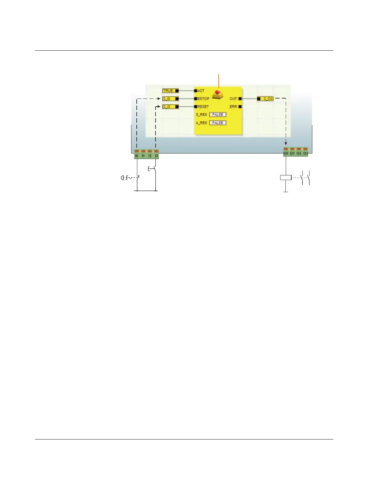
Figure
2-3
Implementing a startup inhibit, rest
art inhibit, and stop category
0 for safe
output O0
K1
23
24
13
14
S1
S2
12
11
14
13
Reset
+24V
Not-Halt
E-S
top
EmergencyS
top
PSR-TRISAFE-S
103503a005.eps
Wiring the safety modu
le with safe control
devices, sensors, and actuators
22
24
Table of Contents
Table of Contents
7
1 For Your Safety
9
Purpose of this Manual
9
General Safety Notes
9
Electrical Safety
11
Safety of the Machine or System
12
Directives and Standards
13
Intended Use
15
Documentation
16
Calling the Online Help in the SAFECONF Configuration Software
16
2 System Description
17
Method of Operation and Structure of the PSR-TRISAFE-S Safety System
17
Typical Structure of a Safety System with PSR-TRISAFE-S
17
PSR TBUS DIN Rail Connector from Phoenix Contact
19
Using the System
20
System Startup and Restart Behavior
21
Implementing a Startup Inhibit, Restart Inhibit, and Stop Category
23
Error Detection in I/O Devices
24
Implementing Cross-Circuit Detection for an Emergency Stop Control Device at Inputs I0 and I1 of the Safety Module
24
Diagnostic Tools
25
Parameterizing Cross-Circuit Detection for a Module Input
25
Simplified Schematic View: Hardware Diagnostics in the Event of an Error at a Safe Functional Block
26
Simplified Schematic View: Wiring Check
27
Example of an Online Tool Tip in the Event of an Error
28
Examples of Tool Tips in the Connection Editor in Offline Mode
28
Password Protection
29
Password Protection for the PSR-TRISAFE-S and SAFECONF
29
Ordering Data
30
System Requirements for the SAFECONF Configuration Software
31
3 Hardware: PSR-TRISAFE-S Safety Module
33
Device Description
33
PSR-TRISAFE-S Safety Module with Screw Connection (Left)
33
Block Diagram for the PSR-TRISAFE-S Safety Module
34
Operating Modes (Status) of PSR-TRISAFE-S
35
Diagram: Possible Operating Modes (Status) for the PSR-TRISAFE-S Safety Module
35
Operating and Indication Elements
36
Diagnostic and Status Indicators
36
Operating and Indication Elements of the PSR-TRISAFE-S Safety Module
36
Confirm" Button
38
Signal Connections
39
Signal Inputs
39
PSR-TRISAFE-S Signal Connections
39
Safe Outputs
40
Alarm Outputs M0 to M3
41
Test Pulse Outputs T0 and T1
41
V Supply Connection
41
Supply Connections A1 and A2
41
Ground Switching Outputs O0- and O1
42
USB Interface
43
Status Bar in the SAFECONF Configuration Software
43
Ifs-Confstick
44
IFS-CONFSTICK on the PSR-TRISAFE-S
44
Installing the Safety Module
45
Mounting the Safety Module
45
Mounting PSR TBUS DIN Rail Connectors
46
Attaching the PSR-TRISAFE-S Safety Module to the DIN Rail
46
Connecting the Supply Voltage
48
Connecting the Supply Voltage at A1/A2 and 24V/0V
48
Connecting the Signal Lines
49
Connection to Screw Terminal Blocks (Left) and Spring-Cage
49
4 SAFECONF Configuration Software
51
Installing SAFECONF
51
Overview of Functions and Features
51
Description of the User Interface
53
Figure 4-1 SAFECONF User Interface
53
Safe Functional Blocks and Functions
55
Operating the SAFECONF Configuration Software
60
Creating the Configuration Project
60
Figure 4-3 Project Wizard for Creating a New Configuration Project, Using a Project Template
60
Adding and Connecting Functions, Functional Blocks, and Signals in the Safety Logic
61
Figure 4-4 Inserting Safe Functional Blocks and Functions from the Toolbox in the Connection Editor
61
Figure 4-5 Opening the Hardware Editor with the Auto-Hide Function Enabled
62
Figure 4-6 Inserting a Signal in the Connection Editor
62
Figure 4-7 Connecting Objects Using a Line
64
Figure 4-8 Connecting Unconnected Signals to Functional Blocks or Functions Using Drag & Drop
64
Device Parameterization in the Safe Parameter Editor
65
Figure 4-9 Opening the Device Parameterization Editor for All I/Os
65
Figure 4-10 Opening the Device Parameterization Editor for One Specific I/O
65
Checking, Downloading, and Starting up the Project
68
Figure 4-14 Jumping to an Error Location in the Safety Logic from the Message Window When Checking the Configuration Project
68
Documenting the Signal Assignment and the Project
69
Simulation Mode in SAFECONF
71
Figure 4-16 Simulation of the Safety Module in SAFECONF
71
5 Configuration and Startup
75
Configuration Overview from a to Z
75
Figure 5-1 Flowchart: Configuration from a to Z (1 of 3)
75
Figure 5-2 Flowchart: Configuration from a to Z (2 of 3)
76
Figure 5-3 Flowchart: Configuration from a to Z (3 of 3)
77
Downloading the Configuration from SAFECONF
78
Figure 5-4 USB Connection between PC and Safety Module
79
Figure 5-5 Message Dialog Box Following Successful Data Transmission
80
Figure 5-6 Confirming the Configuration with the "Confirm" Button
80
Downloading the Configuration Using the IFS-CONFSTICK
81
Figure 5-7: Pressing the "Confirm" Button While Inserting the
82
Uploading the Configuration from the PSR-TRISAFE-S Safety Module
83
Function Test
84
Startup Mode
85
6 Application Examples
89
7 Problems and Solutions
91
General
91
Graphical Connection Editor
92
Device Parameterization Editor
92
Online Communication between SAFECONF and the PSR-TRISAFE-S Safety Module
93
Safety Module Messages
95
A Appendix
97
List of Figures
97
Index
99
Other manuals for Phoenix Contact PSR-TRISAFE-S
Manual
28 pages
5
Based on 1 rating
Ask a question
Give review
Questions and Answers:
Need help?
Do you have a question about the Phoenix Contact PSR-TRISAFE-S and is the answer not in the manual?
Ask a question
Phoenix Contact PSR-TRISAFE-S Specifications
General
Brand
Phoenix Contact
Model
PSR-TRISAFE-S
Category
Control Unit
Language
English
Related product manuals
PSM-EG-RS232/RS422-P/4K
18 pages
Phoenix Contact INTERBUS series
56 pages
CONTACTRON Series
168 pages
FL WLAN 1000 Series
42 pages
Phoenix Contact Axioline F
148 pages
Phoenix Contact IFS-CONFSTICK
168 pages
Phoenix Contact FL WLAN 2100
59 pages
 Loading...