PSR-TRISAFE-S
3-4
PHOENIX CONTACT 103503_en_03
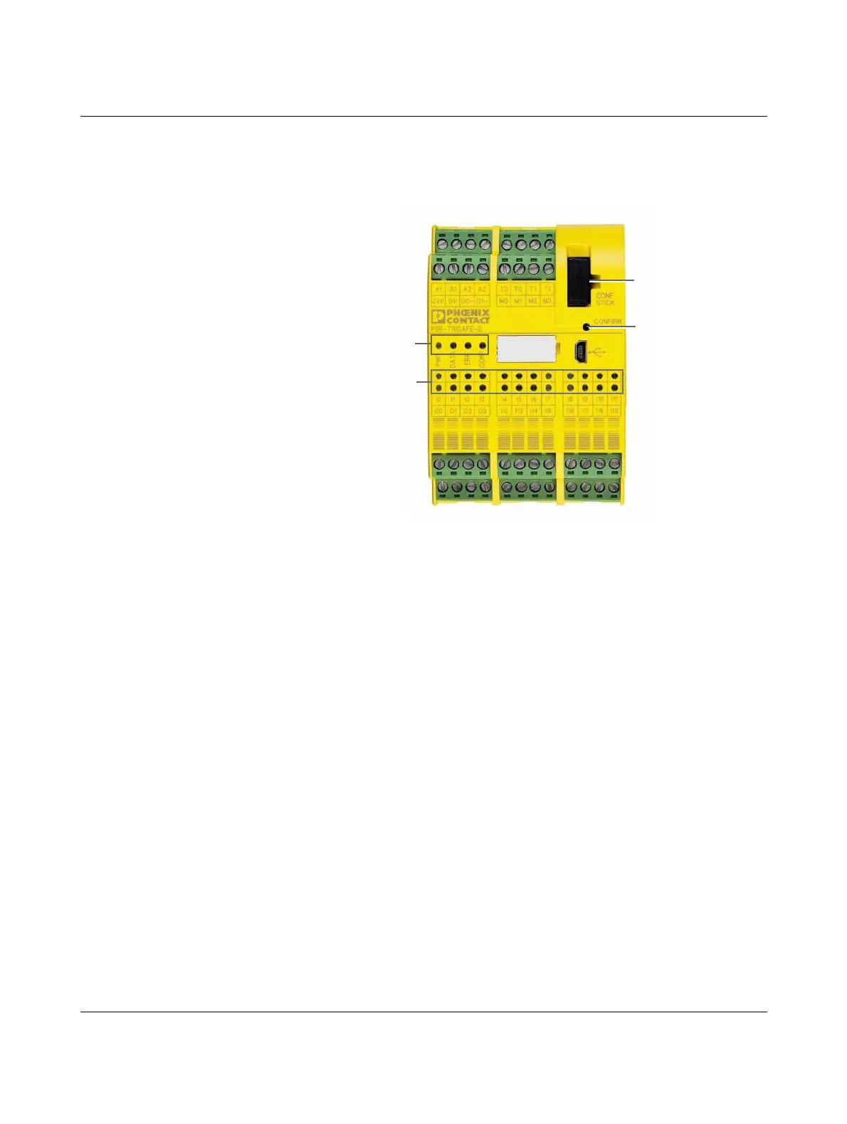
3.3 Operating and indication elements
All operating and indication elements for the PSR-TRISAFE-S safety module are located on
the front of the device. The elements are described in the following sections.
Figure 3-4 Operating and indication elements of the PSR-TRISAFE-S safety module
3.3.1 Diagnostic and status indicators
Status indicators The four status indicators on the front of the device can be used to read the operating status
of the safety module. The following LEDs are available (from left to right):
– "PWR": Indicator for the power supply of the safety module
– "DATA": Indicator for communication with extension devices (with/without PSR TBUS
DIN rail connector). This LED is only on if a TBUS device is connected.
– "ERR": Error indicator
– "CONF": Indicator for the configuration status and communication via the USB interface
The following table lists the possible indicator combinations for the status LEDs and their
meanings. A distinction is made between slow flashing and fast flashing LEDs.
Status indicators
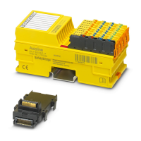
IFS-CONFSTICK
"Confirm" button
LEDs - Status
of the safe I/Os
 Loading...