PDP-5000EX
139
5678
56
7
8
C
D
F
A
B
E
8.2.3 INITIALIZE
8.2.3.1 SYNC DET (+)
8.2.3.2 SG MODE
¶ Operation items
No. Function/Display Content RS-232C Command
1 SYNC DET (+) Only for the technical use. –
2 SG MODE <=> Paired SG_MODE with SG_PATTERN. Set SG Route. –
3 SG PATTERN <=> Paired SG_PATTERN with SG_MODE. Set SG Pattern. –
4 SIDE MASK LEVEL Color setup of side mask.
BSL
GSL
RSL
5 FINAL SETUP (+) Initialize flash memories on virgin product status FST
6 HDMI INTR POSITION (+) Only for the technical use. –
• As this is an item for technical engineers, no information on servicing is available.
SG MODE (selection of the SG routes) and SG PATTERN (selection of signal patterns) are used in combination.
The SG route must be first selected in SG MODE. Then the SG pattern of a signal that is to be transmitted to the
selected route must be selected.
Note ∗: The screen shifts to split-screen display, with the SG MODE screen displayed on the right (sublevel).
Check on the block diagram for the SG generation point and signal routes.
No. Function/Display Content
1 SG OFF SG is set to OFF
5 ANA MVDEC Y MAIN VDEC: Y (Analog output mode: SG VDEC feedback setting)
2 ANA AD RGB AD: RGB
3 ANA AD YCBCR AD: Ycbcr
4 ANA SVDEC Y SUB VDEC: Y (Analog output mode: SG VDEC feedback setting)
∗
6 DIG MVDEC YCBCR MAIN VDEC: YCbCr (color difference digital output mode)
NIITILAIZE
GSMOED<=>
V–D1 3 1060
NMA
A– VD YEC–
–NTV WJ–M7
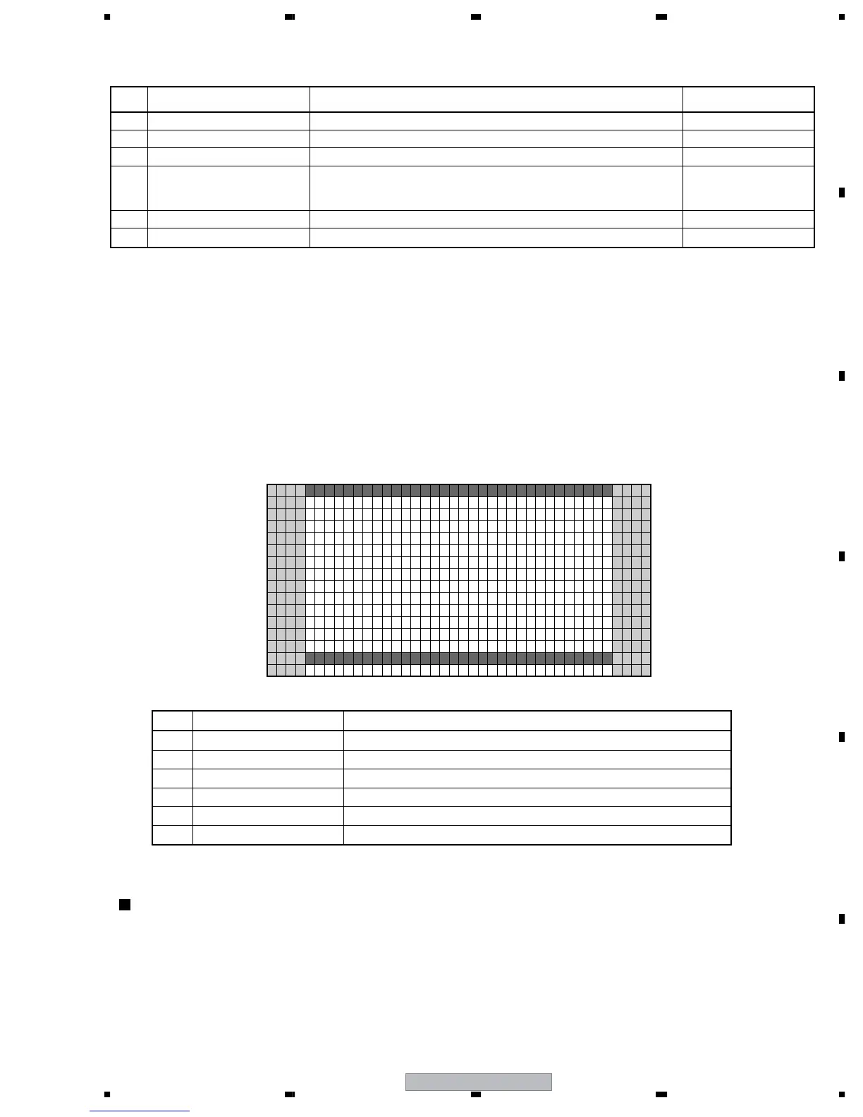
Screen: SG MODE
1
5
10
15
16
15 10 15 20 25 30 35 40
• When the unit is in SG MODE, do NOT input signals to INPUTs 4-6.
• The setting of the Y/C separation function should be set to the NTSC during the VDEC SG mode.
• Only the component and RGB signals can be output during SG mode, so only the Y signal is input at the CVBS signal mode, thus
the picture is composed in black and white color. This isn't a failure.
• ANA AD RGB (the route for inputting the 525i RGB signal to AD) in SG MODE is a setting for a nonexistent route for the unit.
Therefore, there is no setting value at the stages after the MVDEC. For this reason, there may be discoloration of the color bars or
slow change of the luminance after SG MODE is set to ANA AD RGB, but it is not a failure.
Important notice of the SG MODE and SG PATTERN

 Loading...