PDP-5000EX
164
1234
1234
C
D
F
A
B
E
10. GENERAL INFORMATION
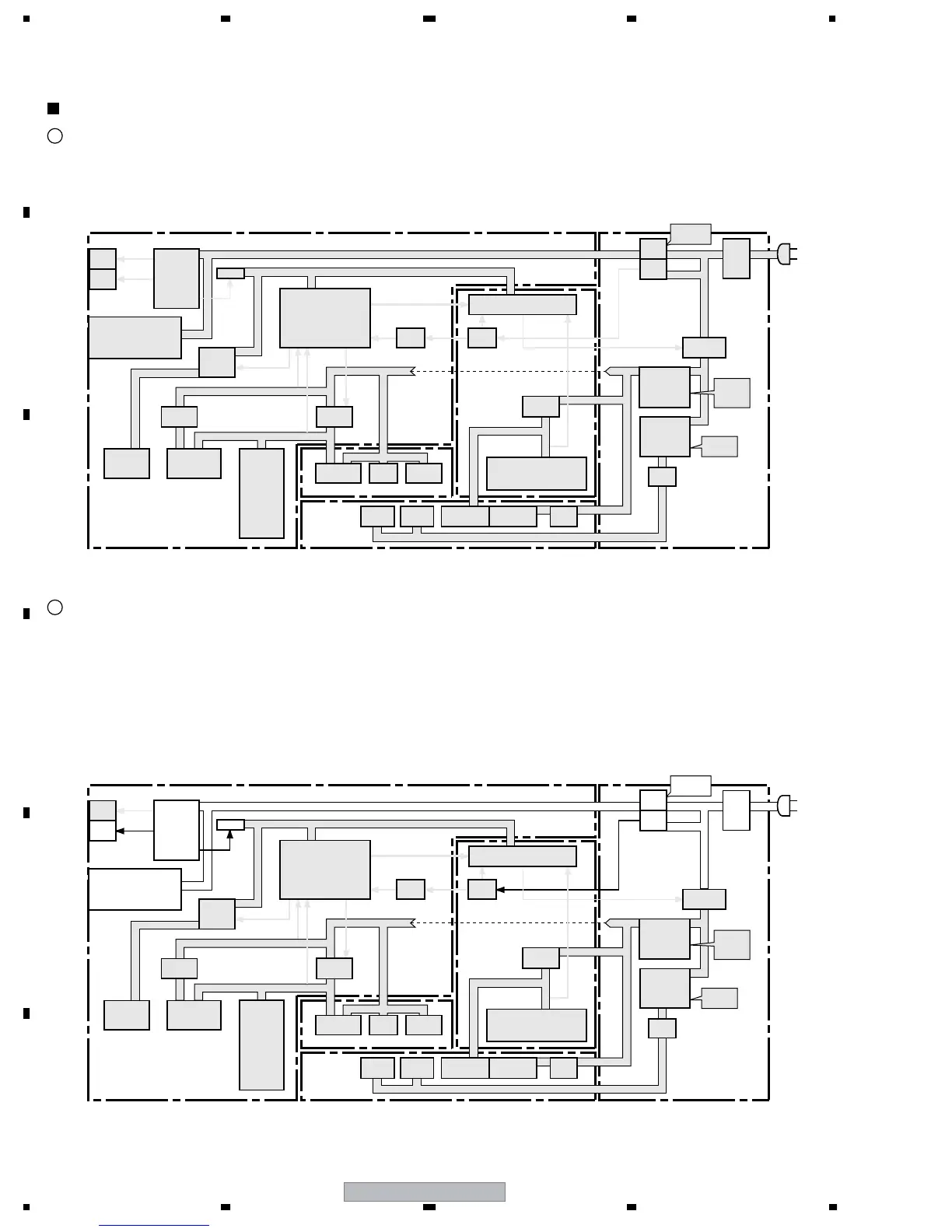
10.1 POWER SUPPLY PROCESS DIAGRAM
Status: No AC power is supplied to the unit at all.
Transition to another mode:
• Plugging in of the AC power cord (AC power is supplied): Shifting to status 3.
• Setting of the MAIN POWER switch to ON (AC power is supplied): Shifting to status 3.
Configuration of the Power System -Power-on status in each mode-
Unplugging of the AC power cord and/or power shutoff at the MAIN POWER switch
1
Status: Power is supplied to only the IF microcomputer and part of its surrounding circuits. The standby mode in most cases is Passive
Standby mode.
Operation: The IF microcomputer deactivates the Active port to "L" (OFF) and the SW to OFF, in order to turn off the power to the Main
microcomputer and the Module microcomputer.
Transition to another mode:
• Unplugging of the AC power cord: Shifting to status 1.
• Setting of the MAIN POWER switch to OFF: Shifting to status 1.
• User operation (using a remote control unit or a side key): Shifting to status 3 (to notify the Main microcomputer).
Then, shifting to status 4, if required
Passive Standby mode
2
LED
MAIN Assy
Drive
System
Assy
Audio System Assy
DIGITAL Assy
POWER SUPPLY
Unit
BLUE
RED
SQ ASIC
Victria
LVDS_Rx
SW
Small Signal
Power
Large Signal
Power
AC
Power
DVI
Video-SW
RGB-SW
Reg.
LVDS Tx
FPGA
MVDEC
SVDEC
AD
HDMI
DSEL
IP
MULTI
Address
Address
Small Signal
Drive
Reg.
Address
Small Signal
Drive
Audio
SW
Volume
IC
Amp.
DCDC
Reg.
ACTIVE
PSW_DVI
RST4
RST2
RST2
RST3
AC_DET
RELAY
PSW1
RS-232C Driver
Remote Control Receiver
Key Scan
STB3.3V
STB5V
V+16.5V
V+12V
V+6.5V
VSUS
VADR
SW
IF µ-com
SW
Main µ-com
INV
DCDC
Reg.
Module µ-com
Buf.
Relay
STB
Power
AC
Det.

 Loading...