PDP-5000EX
152
1234
1234
C
D
F
A
B
E
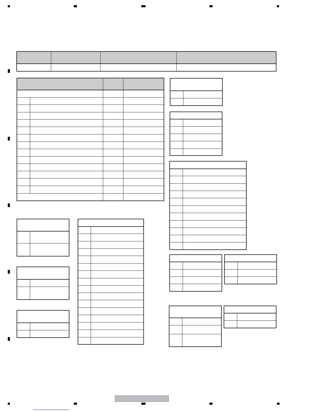
9.3.2 QS2
Data Arrangement
Data
Length
Output Example
ECO 3 Byte QS2
1 Notification of mode shifting to STB 1 Byte 1
2 Flag for adjustment of the main unit 1 Byte 0
3 Flag for adjustment-data backup 1 Byte 0
4 "1st PD" data 1 Byte 0
5 "2nd PD" data 1 Byte 0
6 Still picture detection 1 Byte 0
7 Reserved 2 Byte ∗∗
8 Temperature data (TEMP 1) 3 Byte 128
9 SD main data 1 Byte 0
10 SD subdata 1 Byte 0
11 Operation status induced by SD 1 Byte 0
12 Data from the hour meter 8 Byte 00000259
13 MASK indication 1 Byte 0
CS 2 Byte 4A
1:
Notification of mode
shifting to Standby
0
Entering Standby
mode failed
1
Entering Standby
mode succeeded
2: Adjustment of the
main unit
0
Adjustment completed
1
Adjustment not
completed
3: Adjustment-data
backup
0 With backup data
1 No data
6: Still picture
detection
0 Normal screen
1 Still picture
4, 5: PD data
0 No PD data
1 Not used
2 POWER
3 SCAN
4 SCN-5V
5 Y-DRV
6 Y-DCDC
7 Y-SUS
8 ADRS
9 X-DRV
A X-DCDC
10-1: SD-Sub (SQ-IC)
0 No SD-Sub data
1 Communication error (LR/G7)
2 Drive stop (LR/G7)
3 BUSY
4 Communication error (L)
5 Drive stop (L)
6 Incoherent versions (H/S)
7 Incoherent versions (L/R)
8 Not used
9 Communication error (R)
A Drive stop (R)
B X-SUS
C Not used
D Not used
E Not used
F UNKNOWN
9: SD main data
0 No SD
1 SQ-IC
2 MDU-IIC
3 RST2
4 TEMP
11: Operation status
induced by SD
0 Normal
1 Relay-off completed
2
During warning
indication
13: MASK indication
0 MASK-OFF
1 MASK-ON
Command
Format
Effective Operation
Modes
Function Remarks
[QS2] All operations
To acquire data on operations of the panel
Return data: 3 (ECO)+23(DATA)+2(CS)= 28 Byte
7 Acquisition of panel operation data • • • [QS2]
The command QS2 is for acquiring data on the panel's operations. Basically, this command is used for the module's
microcomputer to inform the main unit's microcomputer of changes in panel operation.
Note : "00000259" of "Data from the hour meter" means
2 hours 59 minuts.
10-2: SD-Sub (IIC)
0 No SD-Sub data
1 EEPROM
2 BACKUP
3 DAC
10-3: SD-Sub (TEMP)
0 No SD-Sub data
1 TEMP1
2 Reserved
• If no power-down is generated, 00 is transmitted. If a power-down is generated, data on power-down points are transmitted, with upper-
level point as 1st PD and lower-level point as 2nd PD.
• The TEMP1 input value (10 bits) is transmitted in 3 bytes in decimal notation (range: 000-999) as temperature data.
Values of 1000-1023 are handled as 999. (During Standby mode, the value retained in RAM is transmitted.)
• As to data on the hour-meter count, minute data (3 bytes) stored in the EEPROM are converted to hour data and described in 6 characters.
These 6 characters and 2 characters representing minute are transmitted. The maximum recording time is 279,620 hours 16 minutes.

 Loading...